ESAB ES 300i Instruction Manual Download Page 26

6 CONTROL PANEL

0463 416 001

- 26 -

© ESAB AB 2017

6.3.1

Hidden TIG functions

There are hidden functions in the control panel. To access the functions, press parameter
selection button for 3 seconds (see section SETTING PANEL for button placement). The
display shows a letter and a value. Select function by pressing the same button. The knob is
used to change the value of the selected function. To exit hidden functions, press the button
for 3 seconds again.
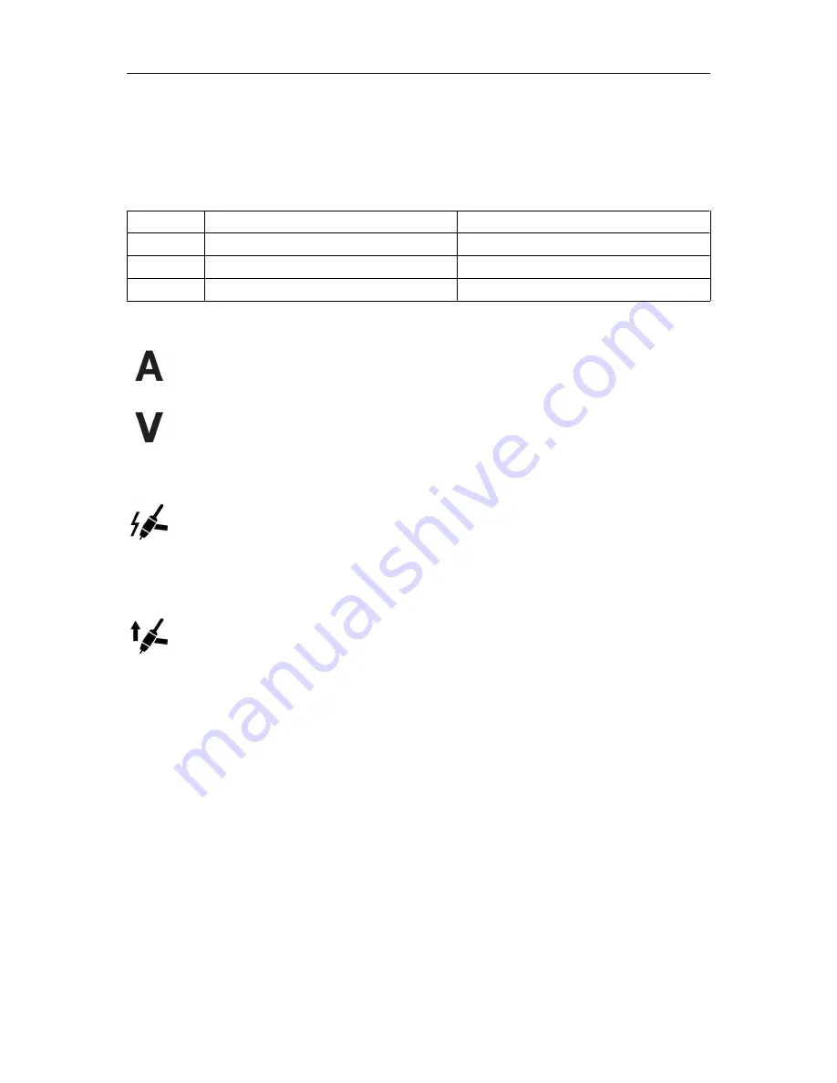
Letter

Function

Settings

A

Gas pre flow

0.0–9.9 s

b

Slope up

0.0–9.9 s

I

Remote min current

0–99%

6.3.2

Measured values

Measured current

Measured value in the display for welding current A is arithmetic average value.

Measured voltage

Measured value in the display for arc voltage V is arithmetic average value.

6.4

TIG functions explanation

HF start

The HF start function initiates the arc by using a high frequency voltage pilot arc.
This will reduce the risk of tungsten contamination in the starts. The high
frequency voltage might disturb other electrical equipment in the surrounding
area.

LiftArc™

The LiftArc™ function initiates the arc when the tungsten electrode is brought
into contact with the workpiece, the trigger switch is pressed, and the tungsten
electrode is lifted away from the workpiece. In order to minimize the risk of
tungsten contaminations the start current is very low and will slope up to the set
current (controlled by the slope up function).

Summary of Contents for ES 300i

Page 1: ...Instruction manual 0463 416 001 GB 20171016 Valid for serial no 721 742 xxx xxxx ET 300i ET 300iP Welding power source TIG 300 A...

Page 2: ......

Page 3: ...5 5 Connection of welding and return cables 18 5 6 Turning the mains power on off 18 5 7 Connect to cooler EC 1000 19 5 8 Fan control 19 5 9 Thermal protection 20 5 10 Voltage reducing device VRD 20 5...

Page 4: ...E 32 7 1 Routine maintenance 32 7 2 Cleaning instruction 32 8 TROUBLESHOOTING 36 9 ERROR CODES 37 9 1 Error code descriptions 37 10 ORDERING SPARE PARTS 39 DIAGRAM 40 ORDERING NUMBERS 41 ACCESSORIES 4...

Page 5: ...y precautions must meet the requirements that apply to this type of equipment The following recommendations should be observed in addition to the standard regulations that apply to the workplace All w...

Page 6: ...ELECTRIC AND MAGNETIC FIELDS Can be dangerous to health Welders having pacemakers should consult their physician before welding EMF may interfere with some pacemakers Exposure to EMF may have other he...

Page 7: ...uipment is not intended for use in residential locations where the electrical power is provided by the public low voltage supply system There may be potential difficulties in ensuring electromagnetic...

Page 8: ...es intended for TIG welding and for welding with covered electrodes MMA ESAB accessories for the product can be found in the ACCESSORIES chapter of this manual 2 2 Equipment The power source is suppli...

Page 9: ...A 10 V 300 A 22 V 5 A 10 V 200 A 18 V Permissible load at MMA 40 duty cycle 300 A 32 0 V 60 duty cycle 250 A 30 0 V 100 duty cycle 200 A 28 0 V 200 A 28 0 V Permissible load at TIG 40 duty cycle 300 A...

Page 10: ...inimum short circuit power on the network in accordance with IEC 61000 3 12 Duty cycle The duty cycle refers to the time as a percentage of a ten minute period that you can weld or cut at a certain lo...

Page 11: ...oduct may cause radio interference It is the user s responsibility to take adequate precautions 4 1 Location Position the power source so that its cooling air inlets and outlets are not obstructed A M...

Page 12: ...an or equal to Sscmin Refer to the technical data in the TECHNICAL DATA chapter The power source will automatically adjust to the supplied input voltage make sure it is protected by the correct fuse r...

Page 13: ...g 1 5 2 Nm 13 3 17 7 in lb A 7 Use two cable ties to fasten the cables D 8 Optional If the fan with foam has been removed it shall now be re installed A symbol on the side of the fan G shows the air f...

Page 14: ...4 INSTALLATION 0463 416 001 14 ESAB AB 2017 1 phase WARNING In 1 phase operation the terminal L3 is powered even though not connected Make sure to keep terminal L3 disconnected...

Page 15: ...length 100 m 330 ft 100 m 330 ft 100 m 330 ft 100 m 330 ft 100 m 330 ft 100 m 330 ft Minimum recommended extension cord size 4 4 mm 4 4 mm 4 4 mm 4 4 mm 4 4 mm 3 6 mm NOTE Different variants of ET 300...

Page 16: ...hieve 200 A in MMA and TIG mode MCB fuses break the circuit faster than porcelain fuses Supply from power generators The power source can be supplied from different types of generators However some ge...

Page 17: ...ARNING Electric shock Do not touch the workpiece or the welding head during operation 5 2 Connections and control devices 1 User interface see chapter CONTROL PANEL 7 Gas supply input 2 Connection TIG...

Page 18: ...or MMA welding the power source shall be supplemented with welding cable with electrode holder return cable with clamp 5 5 Connection of welding and return cables The power source has two outputs a po...

Page 19: ...ce cable does not get squeezed between the power source and the cooling unit NOTE Power supply of the cooling unit is done from the welding power source via the connection cable for more information s...

Page 20: ...trol is activated the control panel is locked for interaction but displays welding data 5 12 USB connection Always use the USB cover when the USB connection is not in use Do not use for charging units...

Page 21: ...ection indicated by 8 to 10 Also used for access to hidden fuctions 5 Button to select 2 stroke or 4 stroke TIG only 12 Overheating indicator 6 Button to activate and deactivate remote control unit 13...

Page 22: ...ue mode will result in automatically move to set current value mode The set indicator is off when measured values are shown 6 1 2 Weld program For each welding process MMA TIG three different weld pro...

Page 23: ...hange between the parameters in the graph 6 Button to activate and deactivate remote control unit 17 Indicates which is shown in the display s seconds for gas pre flow gas post flow slope up and slope...

Page 24: ...et parameter The set indicator 4 will be lit when a displayed value can be changed It cannot be changed from the panel when a remote control is activated Trying to change a value while in measured val...

Page 25: ...X Gas pre flow time H 0 0 9 9 s 0 0 25 0 s 0 1 1 0 s H X Gas post flow time 0 0 25 0 s 0 1 7 0 s X X 2 stroke ON OFF ON X X 4 stroke ON OFF OFF X X Remote control unit ON OFF OFF X X Pulse ON OFF OFF...

Page 26: ...display for welding current A is arithmetic average value Measured voltage Measured value in the display for arc voltage V is arithmetic average value 6 4 TIG functions explanation HF start The HF st...

Page 27: ...e trigger switch 2 to slope up the current to the set current value To stop the welding press the trigger switch again 3 The current will slope down to the pilot level again Release the trigger switch...

Page 28: ...y be 10 Pulse frequency The amount of pulse cycles in a time period The higher the frequency the more pulse cycles per time period When the pulse frequency is set low the weld pool will have time to p...

Page 29: ...s the trigger switch again 3 The current will slope down to the pilot level again Release the trigger switch 4 to terminate the arc The shielding gas will continue to flow in order to protect the weld...

Page 30: ...nnot be changed while welding H Hidden function 6 5 1 Hidden MMA functions There are hidden functions in the control panel To access the functions press parameter selection button for 3 seconds see se...

Page 31: ...urrent changes in response to variations in arc length during welding Use a low value of arc force to get a calm arc with little spatter and use a high value to get a hot and digging arc Arc force onl...

Page 32: ...e more often during severe dusty conditions Before each use make sure that Product and cables are not damaged The torch is clean and not damaged 7 1 Routine maintenance Maintenance schedule during nor...

Page 33: ...source from the mains supply WARNING Wait at least 30 seconds for the capacitors to discharge before continuing 2 Remove the four screws holding the right side panel R and remove the panel 3 Clean th...

Page 34: ...s no dust left on any part of the power source 7 After having finished cleaning the power source reattach the power source panels in the reverse order NOTE When reattaching the right side panel make s...

Page 35: ...7 MAINTENANCE 0463 416 001 35 ESAB AB 2017 8 Tighten the screws on the side panels with 3 Nm 0 3 Nm 26 6 in lb 2 6...

Page 36: ...shielding gas gas flow welding current filler rod placement electrode diameter and welding mode on power source is used Make sure the gas valve on the TIG torch is on No arc Check that display is on t...

Page 37: ...re is sufficient coolant fluid in the cooler The error code will automatically disappear when the coolant has cooled down and is ready for use again If the error persists contact a service technician...

Page 38: ...wer source If the error persists contact a service technician Err 8 Water cooling disabled The hose from the torch is not connected to the cooling unit Action If a water cooled torch is used make sure...

Page 39: ...N 60974 10 Canadian standards CAN CSA E60974 1 and US standards ANSI IEC 60974 1 On completion of service or repair work it is the responsibility of the person s performing the work to ensure that the...

Page 40: ...DIAGRAM 0463 416 001 40 ESAB AB 2017 DIAGRAM...

Page 41: ...RS Ordering number Denomination Type Notes 0445 100 900 Welding power source ET 300i EU 0445 100 920 Welding power source ET 300iP EU 0463 423 001 Spare parts list 0463 424 001 Service manual Technica...

Page 42: ...00 565 0700 300 567 TIG torch TXH 401w 4 m 13 ft TIG torch TXH 401w 8 m 26 ft 0445 045 880 EC 1000 Cooler 0460 330 881 Trolley 0445 197 880 Shoulder strap kit 0700 006 902 Welding cable kit 3 meter in...

Page 43: ...2 Interconnection cable 6 pin 5 m 16 4 ft Interconnection cable 6 pin 10 m 32 8 ft Interconnection cable 6 pin 25 m 82 ft 0445 550 881 ER 1 F Foot pedal 5 m 16 4 ft interconnection cable 6 pin include...

Page 44: ...Henares MADRID Tel 34 91 878 3600 Fax 34 91 802 3461 SWEDEN ESAB Sverige AB Gothenburg Tel 46 31 50 95 00 Fax 46 31 50 92 22 ESAB International AB Gothenburg Tel 46 31 50 90 00 Fax 46 31 50 93 60 SWI...

Reviews: