


7
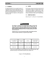
1.1 GENERAL
The patent pending PT-32 is a manual torch with a 75°
head designed for use with several Plasma Arc Cutting
Packages using clean, dry air as the plasma gas. The
service line lengths available with the PT-32 torch are
25 feet (7.6 m) and 50 feet (15.2 m). The PT-32 torch
is rated to operate at a maximum of 90 amperes at
100% duty cycle.
1.2 SCOPE
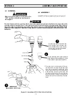
This manual is intended to provide the operator with all
the information required to assemble, operate, and
repair the PT-32 Plasma Arc Cutting Torch. For addi-
tional safety precautions, process instructions, and
system troubleshooting; refer to the appropriate in-
struction manual for your Plasma Arc Cutting Package.
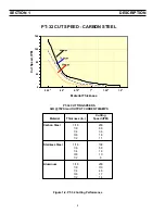
1.3 SPECIFICATIONS
Refer to Figure 1-1 and Figure 1-3 for specifications.
The plasma arc cutting process employs high voltages. Contact with
"live" parts of the torch and machine must be avoided. Also, the
improper use of any of the gases employed can present a safety hazard.
Before beginning operation with the PT-32 torch, refer to the Safety
Precautions and operating instructions in the appropriate power source
instruction manual.
Using the torch on any unit not equipped with a mating safety interlock
circuit may expose operator to unexpected high voltage.
Figure 1-1. PT-32 Specifications
SECTION 1
DESCRIPTION
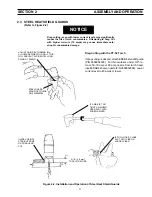
y
l
b
m
e
s
s
A
h
c
r
o
T
)
.
o
N
t
r
a
P
(
e
n
i
L
e
c
i
v
r
e
S
h
t
g
n
e
L
t
h
g
i
e
W
y
ti
c
a
p
a
C
t
n
e
r
r
u
C
)
y
t
u
d
%
0
0
1
(
1
7
9
1
0
0
8
5
5
0
)
m
6
.
7
(
tf
5
2
)
g
k
4
.
2
(
s
b
l
2
.
5
P
S
C
D
A
0
9
2
7
9
1
0
0
8
5
5
0
)
m
2
.
5
1
(
tf
0
5
)
g
k
4
.
4
(
s
b
l
6
.
9
P
S
C
D
A
0
9
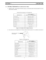
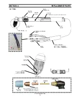
Torches and torch body assemblies purchased individually are supplied without electrode, nozzle,
heat shield and valve pin. Order individual components shown on pages 9 or 15.


