


10
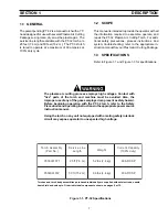
2.1 GENERAL
Make sure power switch on console is in the
"OFF" position and primary input power is
deenergized.
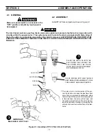
2.2 ASSEMBLY
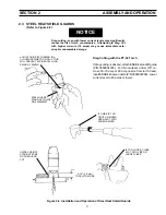
Install PT-32 front end parts as shown in Figure 2-1.
The torch head contains a gas flow check valve and a nozzle back pressure tap that act in conjunction with
circuitry within the power source. This system prevents the torch from being energized with high voltage if
the torch switch is accidentally closed when the shield is removed. ALWAYS REPLACE TORCH WITH THE
PROPER TORCH MANUFACTURED BY ESAB SINCE IT ALONE CONTAINS ESAB'S PATENTED SAFETY IN-
TERLOCK.
!
WARNING
SECTION 2
ASSEMBLY AND OPERATION
*
The valve pin is a crucial member of the sys-
tem. Its function is to open the gas flow check
valve that is permanently assembled within
the torch head. If the pin is not correctly placed
in the electrode, the valve will not open and
the system will not function. The valve pin also
improves electrode cooling by increasing the
velocity of air over the inner surface of the elec-
trode.
VALVE PIN
ELECTRODE
NOZZLE
SHIELD
*
PLACE NOZZLE INTO HEAT SHIELD
AND THREAD THIS ASSEMBLY TO THE
TORCH BODY AND HAND TIGHTEN.
2
3
IMPORTANT!
MAKE SHIELD VERY TIGHT!
PLACE THE VALVE PIN INTO THE
ELECTRODE AND SCREW THE
ELECTRODE INTO THE TORCH
HEAD AND TIGHTEN SECURELY
WITH WRENCH #19120.
1
Figure 2-1. Assembly of PT-32 Torch Front End Parts


