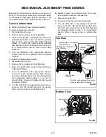
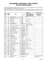
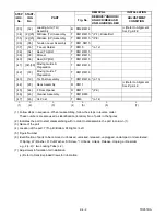
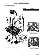

2-4-7
TD951DA
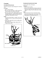
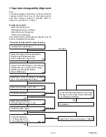
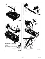
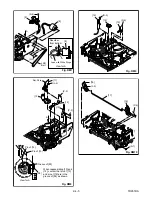
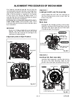
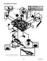
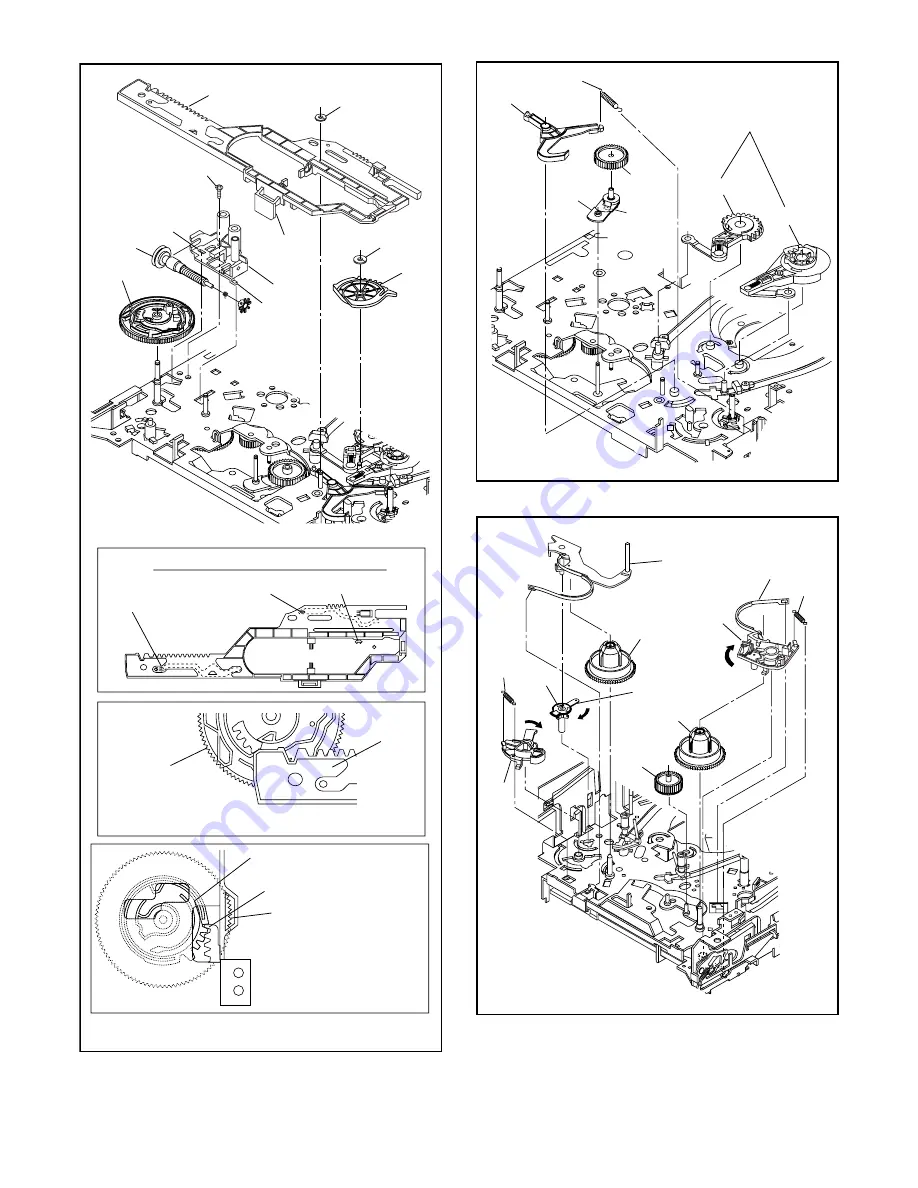
When reassembling [28],
align the first groove on
[28] to the first tooth on
[44] as shown.
[28]
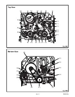
Top View
First tooth on [44]
First groove on [28]
Align [25] and [28] as shown.
Bottom View
[28]
Pin of [34]
Pin of [31]
Position of Mode Lever when installed
Pin of [35]
Fig. DM13
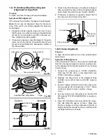
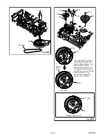
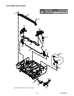
[25]
[24]
(C-3)
(S-9)
[25]
[27]
[26]
[28]
(C-2)
(L-8)
(L-9)
(L-10)
Refer to the Alignment
Section, Page 2-4-9.
Fig. DM14
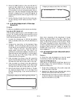
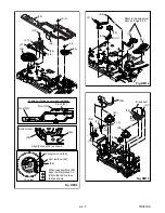
[31]
[30]
[29]
(L-11)
(P-6)
[32]
[33]
Fig. DM15
[35]
[37]
turn
turn
[38]
[39]
[40]
[36]
(P-8)
(P-7)
turn
Break belt
[34]
(L-12)
Summary of Contents for EC720E
Page 2: ...EC720E T1008UJ 2004 06 22 ...
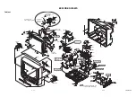
Page 22: ...1 7 4 TD900DC S 4 S 4 S 4 S 4 4 CRT Anode Cap CRT CBA Fig 3 ...
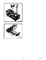
Page 93: ...2 4 8 TD951DA Fig DM16 41 42 43 L 13 44 45 P 9 Slide Fig DM17 ...
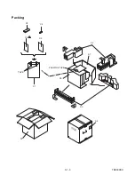
Page 97: ...3 1 3 TD900PEX S4 S1 X1 TAPE X5 X4 X2 X3 S3 S6 S7 S2 PACKING TAPE Packing ...
Page 119: ...Printed in Japan 2003 08 25 HO 6720FDD TD900UA ...