1-7-2
TD900DC
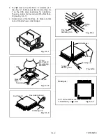
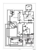
1. Disconnect the following: Anode Cap, CN501, CRT
CBA, CN571, CN2602, and CN1301.
Then remove H.V. CBA (with Holder).
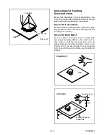
CAUTION 2: Electrostatic breakdown of the laser
diode in the optical system block may occur as a
potential difference caused by electrostatic charge
accumulated on cloth, human body etc., during
unpacking or repair work.
To avoid damage of pickup follow these procedures.
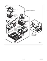
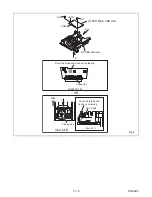
2-1. Short the three short lands of FPC cable with sol-
der before removing the FFC cable (CN201) from
it. If you disconnect the FFC cable (CN201), the
laser diode of pickup will be destroyed. (Fig. 4)
2-2. Disconnect connector (CN301). Remove two
screws (S-7) and lift the DVD Main CBA Unit.
(Fig. 4)
CAUTION 3: When reassembling, confirm the FFC
cable (CN201) is connected completely. Then remove
the solder from the three short lands of FPC cable.
(Fig. 4)
4. Remove screws 7(S-10), 1(S-11), and 1(S-12).
Then, desolder connectors (CL1201, C1401,
CL1402, CL1403) and lift up the Deck Assembly.
S-1
S-2
S-3
S-1
S-1
S-1
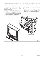
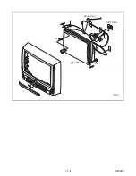
[1] REAR CABINET
Fig. 1
Summary of Contents for EC720E
Page 2: ...EC720E T1008UJ 2004 06 22 ...
Page 22: ...1 7 4 TD900DC S 4 S 4 S 4 S 4 4 CRT Anode Cap CRT CBA Fig 3 ...
Page 93: ...2 4 8 TD951DA Fig DM16 41 42 43 L 13 44 45 P 9 Slide Fig DM17 ...
Page 97: ...3 1 3 TD900PEX S4 S1 X1 TAPE X5 X4 X2 X3 S3 S6 S7 S2 PACKING TAPE Packing ...
Page 119: ...Printed in Japan 2003 08 25 HO 6720FDD TD900UA ...

