18
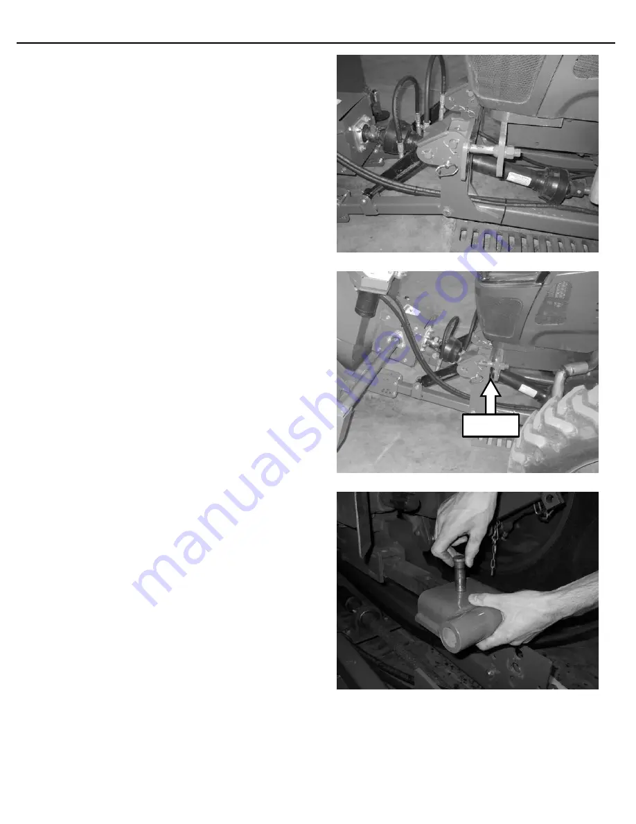
1/4” Gap
MOUNTING INSTRUCTIONS
4. Start the engine and use the remote hydraulic
control lever (see tractor’s owner’s manual) to
lower the push arms. Lowering the push arms
with the frame resting on the ground will cause the
front of the frame to raise. Raise the frame until
the long pin is aligned with the appropriate hole in
the front frame bracket.
5. Drive the tractor forward so the pins are about 1/4"
from fully engaged. This gap is set during the set-
up procedure, and allows the frame to be pushed
from the drawbar rather than pushed from the
front of the tractor. Once properly engaged, fully
raise the snowblower.
NOTE:
In the event that the snowblower is not
sitting level, one of the lift pins is longer to allow
the operator to align the long pin and drive the
tractor forward until the pin engages the hole a
small amount, then slightly raise or lower the push
arms until the shorter pin is aligned with the
appropriate hole in the mounting bracket.
6. Shut down the engine and engage the park brake.
Pin the drawbar bracket to the drawbar and
secure with hairpin. Use shim washers (not
included) if the drawbar is significantly thinner
than the opening in the bracket.
NOTE:
The drawbar bracket can be flipped over
to change the mounting height if needed.
Summary of Contents for 725FM
Page 29: ...29 PARTS INFORMATION ...
Page 31: ...31 725 FM PARTS INFORMATION ...
Page 33: ...33 PARTS INFORMATION ...
Page 35: ...35 PARTS INFORMATION ...
Page 37: ...37 PARTS INFORMATION ...
Page 42: ...42 BOLT TORQUE INFORMATION ...
Page 44: ...44 P N 300732 Date Printed 5 24 2022 Erskine Attachments LLC Printed in U S A ...


