Erskine Attachments 620RP Operator'S Manual Download Page 28

28 


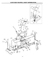
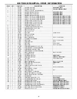
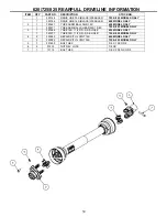
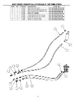
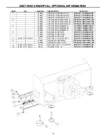
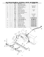
                      620/725/825 REARPULL DRIVE  INFORMATION   


ITEM QTY  PART 

NO. 

DESCRIPTION STOCK 

NO. 

310832 

FAN 20D CCW W/A 

620 MODEL ONLY 


310884 

FAN 24D CCW W/A 

725 & 825 MODELS ONLY 

310837 

SHAFT1.5 X 40.50  FAN REARPULL 


315004 

AUGER 16D X 60 T20 W/A 

620 MODEL ONLY 


315005 

AUGER 16D X 72 T24 W/A 

725 MODEL ONLY 


315006 

AUGER 16D X 84 T24 W/A 

825 MODEL ONLY 

310839 

SHAFT 1.25 X 27.75 AUGER DRIVE 60 

REPLACED BY 330633 OCT 2016 


310835 

SHAFT 1.25 X 33.50 AUGER DRIVE 72 

REPLACED BY 330634 OCT 2016 


310879 

SHAFT 1.25 X 39.50 AUGER DRIVE 84 

REPLACED BY 311769 OCT 2016 

311432 

SHIELD SHAFT 60 PVC X 21 PNT  

REPLACED BY 330638 OCT 2016 


311434 

SHIELD SHAFT 72 PVC X 27 PNT  

REPLACED BY 330640 OCT 2016 


311436 

SHIELD SHAFT 84 PVC X 33 PNT  

REPLACED BY 330642 OCT 2016 

201674 

SPROCKET 50B35 X 1-1/4 B 


310898 

CHAIN ROLLER NO 50 X 98P  C/L 


310368 

BUSHING BP40 1.25 X 1.343 


100832 

BRG 1.25 2-B FLG 


10 

100810 

KEY 5/16 X 1-1/2 


11 

37214 

NUT HEX 

LOCK 1/2 NC 

12 

200322 

BRG 1.5 PLW BLK 


13 

201157 

KEY SQ 3/8 X 2 


14 

200066 

BOLT CARRIAGE 

1/2 X 1 1/4 NC GR 5 

15 

310893 

FLANGETTE 4-B 80MM 


16 

13209 

BOLT HEX 

1/2 X 1 1/2 NC GR 5 

17 2 

33010 WASHER 

FLAT 

7/16" 

18 

36110 

NUT HEX 

FULL 1/2 NC 

19 

13205 

BOLT HEX  

1/2 X 1 NC GR 5 

20 

317287 

WASHER FENDER 1/2" X 2" X 1/8" 


21 

33475 

WASHER MB 1-1/2 14GA NARROW 


22 

310874 

GEAR BEVEL 6DP 24T 1.25B 


23 

33466 

WASHER MB 1-1/4 10GA NARROW 


24 

21817 

BOLT CARRIAGE 

3/8 X 1 NC GR5 

25 

203741 

FLANGETTE 3-B 


26 

103880 

WASHER LOCK 3/8” 

825RP ONLY 


103880 

WASHER LOCK 3/8” 

620RP & 725RP ONLY 

27 

36306 

NUT HEX 

FULL 3/8 NC GR 5 

28 

200054 

KEY SQ 1/4 X 1-1/2 


29 

21818 

BOLT CARRIAGE 

3/8 X 1 1/4 NC GR5 

30 

13103 

BOLT HEX 3/8 X 3/4 NC GR 5 

825RP ONLY 

31 2 

33012 WASHER 

FLAT 

1/2" 

32 

310895 

IDLER PLASTIC 2.5 OD X 2-3/16 


33 

13217 

BOLT HEX 

1/2 X 3-1/2 NC GR 5 

34 

310894 

BRG INSERT 1 1/2 (SS) 


35 8 

33626 WASHER 

LOCK 

1/2" 

36 

202159 

BRG INSERT 1 1/4 SM (SS) 


37 

103071 

SPROCKET 50B13 X 1 1/4 B HT 


38 

310875 

BEVEL GEAR 6DP 24T 1.50 BORE 


40 

26067 

SCREW SET  

3/8 X 3/4 SQ HD 

41 

202830 

WASHER LARGE 3/8 x 1 3/4 

825 RP ONLY 

42 

311448 

SHIM BEARING T24 10GA-4B 

T24 BLOWERS ONLY

43 

201210 

CHAIN OFFSET NO 50 

725 & 825 MODELS ONLY

58 

330633 

AUGER DS 620 1.25 X 28 W/A 

REPLACED 310839 OCT 2016


330634 

AUGER DS 725 1.25 X 34 W/A 

REPLACED 310835 OCT 2016


311769 

AUGER DS 825 1.25 X 39.5 RAW W/A 

REPLACED 310879 OCT 2016

59 

37211 

NUT REV LOCK 5/16 NC GR 5 

COMES WITH SHAFT

60 

201384 

BOLT HEX 5/16 X 1-1/4 NC GR 2 

COMES WITH SHAFT

142 

64137 

PIN ROLL 3/16 X 1-1/2 

FOR 620RP AND 725 RP ONLY


Summary of Contents for 620RP

Page 1: ... u us se e o or r o op pe er ra at te e t th hi is s m ma ac ch hi in ne e u un nt ti il l t th hi is s manual has been read and understood Read the Operation Maintenance Manual entirely When you see this symbol the subsequent instructions and warnings are serious follow without exception Your life and the lives of others depend on it ...

Page 2: ... pertaining to the machine Remember the operator is responsible for the safe operation and maintenance of the machine Most accidents can be prevented Good safety practices not only protect you but also the people around you NOTE Erskine Attachments LLC reserves the right to make improvements in design or changes in specifications at any time without notice and without incurring any obligations to ...

Page 3: ...E MAINTENANCE 11 16 SET UP ASSEMBLY 17 23 PARTS INFORMATION 24 31 GENERAL SPECIFICATIONS 34 WARRANTY 35 REFERENCE INFORMATION Write the serial number for your attachment in the spaces below Always refer to this serial number when calling for service or parts Serial Number _____________ YOUR ATTACHMENTS DEALER ADDRESS PHONE CONTACT ...

Page 4: ...use personal injury and are used with appropriate safety instructions These signal words are not to be ignored your safety is involved CAUTION Indicates a potentially hazardous situation which if not avoided may result in minor or moderate injury WARNING Indicates a potentially hazardous situation which if not avoided could result in death or serious injury DANGER Indicates a potentially hazardous...

Page 5: ...uld occur NEVER allow children or untrained persons to operate DO NOT permit riders on equipment Use adequate safety warning lights and devices as required by local regulations Obey all local laws and regulations regarding machine operation on public property This attachment is designed to move snow only NEVER operate this attachment in a manner other than the intended use Do not modify equipment ...

Page 6: ...portant to refer to the serial number of the attachment when making repairs or ordering parts Early or later models identification made by serial number may use different parts or it may be necessary to use different procedures in doing a specific operation E D A C B F G Serial Plate ...

Page 7: ...ion On each side of blower assembly Quantity 2 C B Part number 201415 Location Back right side of blower Quantity 1 D E Part number 103206 Location Chute rotation chain cover gear shield chain cover on left side Quantity 3 Part number 102957 Location Each side of chute Quantity 2 Part number 102946 Location Front of chute assembly Quantity 1 F Part number 200001 Location Right rear of blower housi...

Page 8: ... 5 inches 127mm Extending beyond these lengths could allow driveline separation and damage will occur Also be sure the driveline does not bottom out when the blower is fully raised 3 If purchased with the hydraulic chute rotation or deflector connect the chute rotator hoses to the couplers Manual rotation is standard NOTE Make sure both the male and female quick couplers are clean before attaching...

Page 9: ...gle must not exceed 20 degrees at any time 2 Skid shoes are used to control the minimum desired cutting depth If necessary to adjust the skid shoes raise and block the snow blower Remove the skid shoe lynch pins and adjust the shoes up or down equally to the desired cutting depth Reinstall the lynch pin WARNING To prevent personal injury never work on a raised implement without using additional su...

Page 10: ... disengaging the PTO 9 Select the tractor gear that best suits the conditions and operate the engine at full throttle Start the tractor moving forward into the snow Blow the snow toward a clear area When possible direct snow discharge downwind NOTE Tractor forward speed can be varied according to tractor power snow depth and density Always operate at full throttle when blowing snow for maximum sno...

Page 11: ...to rest on the skid shoes shut down the engine wait for all motion to stop and set park brake before leaving the operator s seat to perform service of any kind Use No 2 lithium base gun grease when lubricating all Snow Blower grease fittings Grease the three chute roller guides every 8 hours of operation IMPORTANT These are requirements It is the responsibility of the owner operator to make sure t...

Page 12: ... slide with the driveline compressed Grease the bearing on the front end of the fan shaft after every 40 hours of operation Use clean engine oil to lubricate the auger drive chain and the chute rotator chain after every 40 hours of operation ROUTINE SNOW BLOWER MAINTENANCE____________ LUBRICATION continued 40 40 4 ...

Page 13: ...cking bolt to prevent the roller from rotating IMPORTANT Do not overtighten roller chains Tighten only enough to remove slack After the snow season is over we recommend greasing the auger drive gears to prevent excessive corrosion To do this remove the top cover and apply a generous amount of grease to the gear teeth It is a good idea to inspect the gears at this time for excessive wear or play Tu...

Page 14: ...earbox under a shield If sheared align the holes in the coupler flange and install a 5 16 x 1 1 4 NC Grade 2 bolt B and lock nut A If the shaft and coupler need to be separated unscrew the grease zerk C and release the retaining steel ball through the grease zerk hole Reverse these steps to reassemble Hydraulic Rotation To adjust the discharge chute roller chain 1 Remove the two bolts securing the...

Page 15: ...USTMENT continued Manual Rotation To adjust the discharge chute cable 1 Rotate chute all the way to side needing adjustment 2 Loosen the setscrew holding the cable in place 3 Using pliers pull the cable through the hole until the cable is tight 4 Tighten the setscrew in place ...

Page 16: ...t the crank tube Bolt the lower end of the crank tube to the spool The crank handle length is adjustable Start with it in the shortest position until you can mount the blower to the tractor IMPORTANT Make sure the crank handle will not contact you or any part of the tractor through the entire range of motion UNCRATING AND SETUP ...

Page 17: ...and lock nut IMPORTANT Tighten each lock nut to 75 ft lbs Rotate the chute so it is facing the front right corner of the blower body as shown Feed one end of the cable through the rear hole of the spool through the cable guide link and around the back of the chute as shown Use an Allen wrench to lock the cable in place leaving a short tail sticking out Run cable through chain links backwards in su...

Page 18: ...kwise as viewed from above The position of the chute does not need to be exact but can be varied to help with the next step Thread the remaining end of the cable though the spool as shown The crank position can be changed slightly to aid in the threading of the cable and the tightening of the Allen screw Make sure the cable on the spool remains tight Pull all the slack out of the cable before tigh...

Page 19: ...TANT Tighten each lock nut to 75 ft lbs Rotate the chute to the straightforward position Loosen the motor mounting bolts Push the motor all the way towards the chute Install the No 40 roller chain around the sprocket Tighten the chain by moving the motor outward to remove all slack in the chain Tighten the motor bolts CAUTION Do not operate the snow blower without the chain shield in place Install...

Page 20: ..._ DRIVELINE INSTALLATION Install keyed yoke of the driveline onto the snow blower gear box shaft with a 3 8 x 2 key Secure with 3 8 grade 5 bolt and tighten set screw WARNING Be sure the PTO master shield is secured in its operating position ...

Page 21: ...to be tilted rearward somewhat in order to create a straighter driveline angle from the tractor PTO shaft to the snow blower gearbox This can be accomplished by lengthening the tractor s upper 3 point arm The degree of backward tilt depends on tractor size and PTO location EXAMPLE The higher the tractor PTO shaft is above the ground the more backward tilt is required IMPORTANT It is extremely impo...

Page 22: ...e is less than 4 of overlap contact your dealer 5 Start the tractor and slowly raise the 3 point system checking to be sure the driveline does not bottom out before reaching the highest position Also check that there is sufficient clearance between the driveline and the drawbar If not consult the tractor owner s manual to learn how to adjust or remove it IMPORTANT Severe damage to the tractor may ...

Page 23: ... blower If there is any roughness or excessive noise stop the blower shut down the tractor engine and find the cause Adjust or replace any parts as needed You are now ready to blow snow See the section in this manual titled Operating the Snow Blower MOUNTING AND ADJUSTING BLOWER TO TRACTOR continued ...

Page 24: ...YD CHUTE ROT PKG 15 1 103329 MOTOR HYD 2 8 CID HYD CHUTE ROT PKG 16 2 13209 BOLT HEX 1 2 X 1 1 2 NC GR 5 HYD CHUTE ROT PKG 17 8 33010 WASHER FLAT 7 16 725 825 MODELS ONLY 1 33010 WASHER FLAT 7 16 HYD CHUTE ROT PKG 18 2 37820 COUPLING NUT 3 8 X 1 3 4 ZINC HYD CHUTE ROT PKG 19 3 13213 BOLT HEX 1 2 X 2 1 2 NC GR 5 20 3 315155 ROLLER GREASABLE BUSHING 21 3 315020 ROLLER CHUTE 22 2 310860 SHIELD GEARS ...

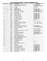
Page 25: ...25 620 725 825 REARPULL BODY INFORMATION__________ ...

Page 26: ...IN LYNCH 7 16 34 1 310841 FRAME ARM REARPULL T20 RH W A 620 MODEL ONLY 1 311418 FRAME ARM REARPULL T24 RH W A 725 825 MODELS ONLY 35 1 104397 PIN 3 PT UPPER CAT 1 36 8 13207 BOLT HEX 1 2 X 1 1 4 NC GR 5 37 2 13317 BOLT HEX 5 8 X 3 1 2 NC GR 5 38 1 311404 BRACKET CRANK HOLDER TRP PAINTED 311403 UNPAINTED 39 2 13210 BOLT HEX 1 2 X 1 3 4 NC GR 5 40 1 310864 CROSSMEMBER TRP20 W A 620 MODEL ONLY 1 3114...

Page 27: ...27 620 725 825 REARPULL BODY INFORMATION________ ...

Page 28: ...18 8 36110 NUT HEX FULL 1 2 NC 19 1 13205 BOLT HEX 1 2 X 1 NC GR 5 20 1 317287 WASHER FENDER 1 2 X 2 X 1 8 21 1 33475 WASHER MB 1 1 2 14GA NARROW 22 1 310874 GEAR BEVEL 6DP 24T 1 25B 23 1 33466 WASHER MB 1 1 4 10GA NARROW 24 3 21817 BOLT CARRIAGE 3 8 X 1 NC GR5 25 4 203741 FLANGETTE 3 B 26 7 103880 WASHER LOCK 3 8 825RP ONLY 6 103880 WASHER LOCK 3 8 620RP 725RP ONLY 27 6 36306 NUT HEX FULL 3 8 NC ...

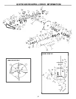
Page 29: ...29 620 725 825 REARPULL DRIVE INFORMATION VIEWED FROM TOP VIEWED FROM FRONT ...

Page 30: ...YOKE ASSM BALL SHR 14S 620 MODEL ONLY 1 320371 YOKE ASM BALL SHEAR 35S 1 3 8S 725 825 MODEL ONLY 3 1 320384 YOKE 14S 1 1 2 RD SS HOLE 620 MODEL ONLY 1 320377 YOKE 35S 1 1 2 RD SS HOLE 725 825 MODEL ONLY 4 2 320243 REPAIR KIT U JOINT 14S 620 MODEL ONLY 2 320385 REPAIR KIT U JOINT 35S 725 825 MODEL ONLY 5 1 201600 BOLT HEX 3 8 X 1 NC GR 2 6 2 37212 NUT REV LOCK 3 8 NC 7 1 13114 BOLT HEX 3 8 X 2 3 4 ...

Page 31: ...R PKG 5 1 320659 ADPT RESTRICTOR 10MB 6MJ 1 32 OPT HYD ROTATION PKG 6 3 201522 ADPT STR 10MB 6MJ OPT HYD ROTATION PKG 201522 ADPT STR 10MB 6MJ OPT HYD DEFLECTOR PKG 7 2 200248 COUPLER HYD PPT 1 2 10OR M OPT HYD ROTATION PKG 2 200248 COUPLER HYD PPT 1 2 10OR M OPT HYD DEFLECTOR PKG 8 2 310892 HOSE 1 4 X 90 6FJX 6FJX OPT HYD ROTATION PKG 9 2 310891 HOSE 1 4 X 10⁴ 6FJX 2MP OPT HYD DEFLECTOR PKG ...

Page 32: ...2 1 300603 CUTTING EDGE RUBBER 57 OPTIONAL RUBBER PKG 1 300604 CUTTING EDGE RUBBER 69 OPTIONAL RUBBER PKG 1 300606 CUTTING EDGE RUBBER 81 OPTIONAL RUBBER PKG 3 1 315463 BACKING PLATE SB 57 WITH OPT URE RUB PKG 1 315464 BACKING PLATE SB 69 WITH OPT URE RUB PKG 1 315466 BACKING PLATE SB 81 WITH OPT URE RUB PKG 5 6 60 7 72 8 84 13211 BOLT HEX 1 2 X 2 NC GR 5 WITH OPT URE RUB PKG 6 2 315467 SKID SHOE ...

Page 33: ...NC GR 5 13 2 13469 BOLT HEX 1 X 4 NC GR 5 14 4 37212 NUT REV LOCK 3 8 NC 15 2 37219 NUT REV LOCK 1 NC 16 1 315460 CUTTING EDGE URE 69 SB OPT URETHANE PKG 72 1 315462 CUTTING EDGE URE 81 SB OPT URETHANE PKG 84 1 300604 CUTTING EDGE RUBBER 69 SB OPT RUBBER PKG 72 1 300606 CUTTING EDGE RUBBER 81 SB OPT RUBBER PKG 84 17 1 315464 BACKING PLATE SB 69 OPT URE RUB PKG 72 1 315466 BACKING PLATE SB 81 OPT U...

Page 34: ...lade Auger Diameter 16 open flighting 16 open flighting 16 open flighting PTO Speed 540 RPM 540 RPM 540 RPM Chute Rotation Manual 210 Manual 210 Hydraulic 270 Cutting Edge Bolt on 5 8 x 6 Bolt on 5 8 x 6 Bolt on 5 8 x 6 Driveline 14 series 35 series 35 series Casting Distance up to 30 up to 40 up to 40 HP Range 20 35 30 55 40 75 Hitch Requirement Cat I Cat I Cat I Shipping Weight Approx 840lbs App...

Page 35: ...e liable for incidental or consequential damages or injuries including but not limited to the loss of profit rental or substitute equipment or other commercial loss Purchaser s sole and exclusive remedy being as provided here in above Erskine Attachments LLC must receive immediate notification of defect and no allowance will be made for repairs without our consent or approval This warranty is in l...

Page 36: ...36 P N 300620 Date Printed 2 27 2017 Erskine Attachments LLC Printed in U S A ...

Reviews: