background image


37 

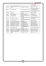
stabilize mains 

Error 18 

Control board system tension 

failure 

Damaged control board 

Remove control board 

Error 19 

Room temperature 

Room temperature too high 

Door open in slow motion 

ad remain stoped until 

working temperature is cool 

Error 20 

Trapment 

Door has trapped a person or 

obstacle 

Remove obstacle 

Error 21 

Damaged battery 

Battery has no power 

Remove battery 

Error 22 

Battery unloaded 

Battery has less power than 

necesary 

Led battery to charge 

Error 23 

Emergency  ( fire alarm) 

Emergency fire alarm input is 

activated 

Disable emergency or fire 

alarm signal 

Error 24 

Continuous trapment 

Door has trapped a person or 

obstacle 

Remove obstacle 

Error 25 

Internal photoceel test failure 

Damaged photocell 

Remove photocell 

Error 26 

External photocell test failure 

Damaged photocell 

Remove photocell 

Error 27 

Safety sensor 1  test failure 

Damaged safety sensor 

Remove safety sensor 

Error 28 

Safety sensor 2  test failure 

Damaged safety sensor 

Remove safety sensor 

Error 29 

Panic breakout input 

Panic breakout leave are 

released 

Lock panic breaout leaves 

Error 30 

Relay K1 ( motor switch) failure 

Damaged control board 

Remove control board 

Error 31 

Relay K2 ( power switch) failure 

Damaged control board 

Remove control board 

Error 32 

Relay K3 ( bus power switch) 

failure 

Damaged control board 

Remove control board 


Summary of Contents for ERTAIN 4 SYSTEM

Page 1: ...ERTAIN 4 SYSTEM ACTUATOR FOR SLIDING DOORS INSTALLATION MANUAL...

Page 2: ...ork ERREKA Automatic Doors will not be held liable for any damages caused by an installation not in accordance with this Installation Manual Revisi n No Date Modifications 02 21 12 17 ERTAIN 4 operato...

Page 3: ...rds Follow the instructions of all the elements fitted in the installation Erreka Automatic Doors shall not be held liable for the safe and smooth operation of the door when system components other th...

Page 4: ...ing speed 0 1 0 5 m s Maximum closing force 150 N Temperature 20 C 50 C Door open timing 60 sec Power Supply 230 V 10 50 Hz Consumption 100 W Batteries Ni Cd 24 v Available upon request the version of...

Page 5: ...the installation For your information the following diagram shows of the profiles and external dimensions of the motorization 1 2 3 1 Perfil Caja 2 Perfil Tapa 3 Goma antivibraci n 165 135 60 35 15 1...

Page 6: ...165 135 35 73 95 65 steps 1 Mark the installation height of the support profile The profile must be set at 35mm from the base of the beam wall structure 2 Place side covers fixing them to the support...

Page 7: ...es to the sliding leaves Secure the leading edge brackets to the sliding leaves as in the drawing the centre of the leading edge must be approx 130 mm from the sides of the moving sheet Fasten the M8x...

Page 8: ...f with the block inserted into the sliding leaf guide mark the ground when the blade is level Then secure the guide to the ground and slide the leaf over the guide 6 9 Height Adjustment of the Leaves...

Page 9: ...rommets to attach the cables which are supplied and placed in the support profile see the picture below Wires WIRING POSITION 6 12 Attaching the arms of the carrierss 2 Sliding leaves Fix the separati...

Page 10: ...the support profile Move the assembly inward so that it fits into the tabs Once seated the motorization can be released Position the motorisation to the side depending on the type of installation Pus...

Page 11: ...the belt Tense the belt from tensor pulley Turn the tensor screw with n 10 spanner and fasten two screws with n 4 allen wrench Tensor screw Detail A One the belt is tensed fasten these scews 6 15 Sec...

Page 12: ...5 mm diameter holes at both ends of the cover profile The distance from the centre of the hole to the end should be 12mm Attach the hanging system cables one at each end of the machine to the support...

Page 13: ...Place the Unlock puller 5 at one end of the support profile right or left as per installation Slide the Case 7 between the Unlock Cable Support 4 and Puller 6 Pass the Cable 8 from the Electrolock to...

Page 14: ...en impulse close impulse input terminal External key J7 Programmable input terminal J8 Safety sensor 1 input terminal J9 Safety sensor 1 input terminal J10 Programmable output terminal J11 Electrolock...

Page 15: ...14 7 3 Components and peripheral standard connection ERTAIN 4 GLOBAL 4 OPERATOR CONTROL BOARD...

Page 16: ...an ON OFF switch a network filter and a 2 A protection fuse To remove the fuse you have to take out the plastic cover Warning Ensure to remove the mains before connecting power supply wires Pass the...

Page 17: ...the battery will not activate as the motor will not have power so it will stay in manual mode Standby mode When the power supply fails the batteries will give power to the control board and periphera...

Page 18: ...installed have a test input to monitor and ensure there are working properly Therefore by default the input should be set up with test mode Before every closing cycle the control board will check the...

Page 19: ...X X X ON X Technical menu Setup Basic functions Advan functions Sensors Movement param Sensors Activ Sensors Photocells Safety sensors Test activation Photocells Internal External Interior NC with te...

Page 20: ...ernal sensor wires directly from the center of the operator or passing them to the edge of the operator from the left hand side View the following diagram to make the connections Connections Sensor se...

Page 21: ...D 12 Hotron SSR 3 Control board Sensor set up Dip switch Y Activation Output NO 2 RAD 13 Hotron 3H IR14 Control board Sensor set up RAD 9 Hotron HR 50 Control board Sensor set up Dip switch Activation...

Page 22: ...n order to monitorize them and to ensure they work properly Therefore by default input will be set up with test If the input has to be modified navigate to the technical menu To access the Technical m...

Page 23: ...safe releases the door by default Therefore depending on the use or commisioning features we advise using one or the other If the door is in emergency escape routes Failsafe electrolock If the doors a...

Page 24: ...chosen option Technical menu Setup Basic functions Advan functions Sensors Movement param Basic functions Type of door Motor type Motor turn sense Electrolock Electrolock Type Test Type Failsafe Fail...

Page 25: ...or The display is usually in energy saving mode with low light until any button is pushed at which point the display will fully light up and any parameters and configuration are displayed When the doo...

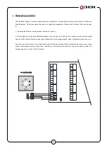
Page 26: ...6 modes 2 Error diagnosis does not differentiate between error modes To determinr the specific error connect the digital selector When the led blinks for one second it indicates that it is working pro...

Page 27: ...pens the door and after one second in open position it closes Beside that the operator pass to the working mode that define the selector digital or key one Even if we are activating KC it does the ope...

Page 28: ...ames The magnetic contact of the profile has to be connected to this input When the magnetic contact is opened the door will go to the open position and remain open until the signal of the magnetic co...

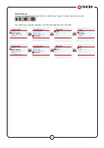
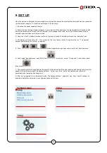
Page 29: ...rror 01 This means set up is not done and the set up must be run The operator cannnot start working until set up is complete 5 Push and buttons together during one second to enter into technical menu...

Page 30: ...atic This allows traffic to exit to the exterior In this direction it works as two way automatic and for people exiting and as a Door Closed mode for people entering 5 Winter mode partial automatic Th...

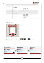
Page 31: ...Technical menu Push at the same time and for one second Once inside menu to choose the paramater you wish to adjust push the down or up buttons To go down and to go up To accept select or move fordwar...

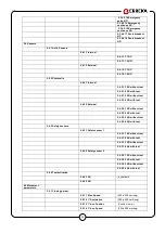
Page 32: ...rameters 1 1 1 Door open time 0 a 20 sec 1 1 2 Opening speed 10 technical menu values 1 1 3 Closing speed 10 technical menu values 1 1 4 partial opening winter opening position from 0 to max opening m...

Page 33: ...al menu push at the same time and buttons during one second It s a programation level allowed for Tecnical service It s necesary to have technical knowledge to adjust the proper parameters In the disp...

Page 34: ...2 3 Motor turn sense 2 2 3 1 Clockwise 2 2 3 2 Anticlockwise not available 2 2 4 Electrolock 2 2 4 1 type 2 2 4 1 1 FailSafe 2 2 4 1 2 FailSecure 2 2 4 1 3 Bistable 2 2 4 1 4 OFF 2 2 4 2 Test microswi...

Page 35: ...2 External 2 4 2 2 1 NC without test 2 4 2 2 2 NC with test 2 4 2 2 3 NO without test 2 4 2 2 4 NO with test 2 4 3 Safety sensors 2 4 3 1 Safety sensor 1 2 4 3 1 1 NC without test 2 4 3 1 2 NC with te...

Page 36: ...seg 2 5 3 Reverse movemement 2 5 3 1 Slow reverse Position Position in mm 2 5 3 2 Normal reverse Position Position in mm 2 5 3 3 Fast reverse Position Position in mm 2 6 Access code 2 6 1 Code change...

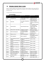
Page 37: ...river temperature is cool Error 6 Motor overcurrent Motor brushes damaged Remove motor Error 7 Motor temperature Motor is overheated Door will open slowly and stop until motor temperature is cool Erro...

Page 38: ...alarm signal Error 24 Continuous trapment Door has trapped a person or obstacle Remove obstacle Error 25 Internal photoceel test failure Damaged photocell Remove photocell Error 26 External photocell...

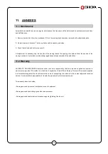
Page 39: ...cordance with existing regulations and requirements of the authorities 11 2 Warranty AUTOMATIC DOORS ERREKA declares under their sole responsibility that the products supplied are subject to warranty...

Page 40: ...owing directives Low voltage directive 2006 95 CE Electromagnetic compatibility directive 2004 108 CE Machinery directive 2006 42 CE Erreka Automatic Doors declares that ERTAIN 4 operator has been des...

Page 41: ...uertas sur erreka com ERREKA CATALUNYA Avda Puig dels Tudons 3 nau 36 Pol Ind Santiga 08210 Barber del Vall s Barcelona Tel 93 729 07 77 Fax 93 729 07 93 puertas catalunya erreka com ERREKA NOROESTE M...

Reviews: