iii
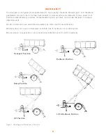
Figure 1. Operating and Maintenance Positions ............................................................................................................................ 2
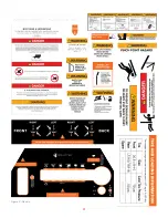
Figure 2. Decals .......................................................................................................................................................................................... 3
Figure 3. Danger Decal, Electrocution Hazard ................................................................................................................................ 5
Figure 4. Equipter Positioned Under Roof. ....................................................................................................................................... 8
Figure 5. Equipter dumping into truck. .............................................................................................................................................. 8
Figure 6. VIN Label, Tire and Loading Information Placard. ....................................................................................................... 9
Figure 7. Connection to Tow Vehicle................................................................................................................................................. 10
Figure 8. Wheel Lift Lever. ................................................................................................................................................................... 10
Figure 9. Chains, Latch, Break-Away Cable. .................................................................................................................................. 11
Figure 10. Platform Latch and Wheel Lift Safety Lock. ............................................................................................................ 11
Figure 11. Parking Brake Lever.......................................................................................................................................................... 12
Figure 12. Fluid Levels. ......................................................................................................................................................................... 13
Figure 13. Grease Fittings Locations. .............................................................................................................................................. 13
Figure 14. Ignition Switch, Choke, Fuel Shutoff and Pull Start. ............................................................................................ 15
Figure 15. Throttle at Operator Station. .......................................................................................................................................... 15
Figure 16. Forward/Reverse and Steering Levers. .................................................................................................................... 16
Figure 18. Outrigger Levers. ............................................................................................................................................................... 16
Figure 17. Bubble Level Indicator. ......................................................................................................................................................17
Figure 19. Decal-Raise or Lower Steering Wheels. ....................................................................................................................17
Figure 20. Front Outriggers with blocking. .....................................................................................................................................17
Figure 21. Rear Outriggers with blocking. ......................................................................................................................................17
Figure 22. Decal-Operator Contact Possible ................................................................................................................................ 18
Figure 23. Flaps Open Under Roof. .................................................................................................................................................. 18
Figure 24. Roll Back, Lift, Dump and Tailgate Levers. .............................................................................................................. 19
Figure 25. Dumping debris from Dump Box.................................................................................................................................. 19
Figure 28. Rear Extension Rails Stored. ......................................................................................................................................... 20
Figure 29. Rear Extension Rails Installed. ..................................................................................................................................... 20
Figure 26. Preparing to Store the Mats. ......................................................................................................................................... 21
Figure 27. Mat Storage. ......................................................................................................................................................................... 21
Figure 30. Chutes in Use. ..................................................................................................................................................................... 21
Figure 31. Chute and Spouting Guard Storage. .......................................................................................................................... 22
Figure 32. VIN Label, Tire and Loading Information Placard. ................................................................................................. 25
I L L U S T R A T I O N S
Summary of Contents for RB4000
Page 2: ......
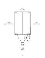
Page 6: ...iv RIGHT Hydraulic Tank Side REAR Tail Gate LEFT Operator Side FRONT Hitch ...
Page 9: ...3 Figure 2 Decals ...
Page 45: ......
Page 46: ...855 378 4783 www equipter com 49 Eagle Drive Leola PA 17540 ...


