background image

21

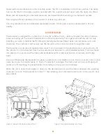
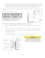
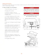
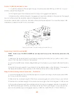
Figure 30. Chutes in Use. 

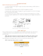
Mats allow the Equipter to traverse areas that would normally be damaged by a vehicle driving across. The 
mats distribute the load across a wider foot print, provide improved traction on slippery surfaces, and are 
lightweight and portable.

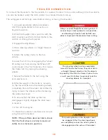
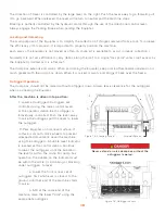
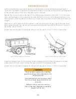
The mats store under the dump bed, sliding in from the rear. To store or remove the mats the dump bed 
must be dumped slightly to allow sufficient clearance. After sliding them into the storage position, the 
dump bed must be lowered back to the transport position.

Figure 26. Prepairing to Store the Mats. 

Figure 27. Mat Storage. 

O P T I O N A L   M A T S

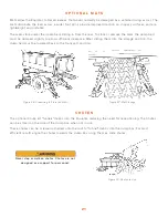
The optional Chute kit “funnels” debris into the Equipter, reducing the need for repositioning. The Chutes 
can be stored on the side of the dump box when not in use.

These chutes can be screwed or nailed onto the roof to “funnel” debris into the dump box. For most 
efficient results angle the chutes towards the dump box using them as slide chutes.

C H U T E S

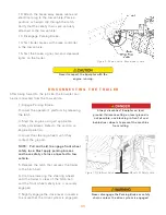
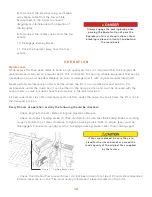
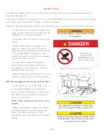
Never step or walk on chutes. Chutes are not 

designed as a support for personnel.

Summary of Contents for RB4000

Page 1: ...R B 4 0 0 0 O P E R A T O R S M A N U A L 855 378 4783 www equipter com 49 Eagle Drive Leola PA 17540 ...

Page 2: ......

Page 3: ...prior written permission of New Heights LLC Additional manuals can be ordered for a fee from New Heights LLC 717 768 0070 The information in this manual is provided to promote the safe use of and assist the operator in achieving the best performance from Equipter products described herein for their intended applications D I S C L A I M E R Copyright 2019 by New Heights LLC Covered by Patent Number...

Page 4: ... Maintenance 12 Engine Operation 14 DRIVING THE EQUIPTER 15 Loading and Unloading 16 Outrigger Operation 16 DUMP BOX 18 Emptying the Dump Box 19 EXTENSION RAILS 20 OPTIONAL MATS 21 CHUTES 21 SPOUTING GUARD 22 CHUTE AND SPOUTING GUARD STORAGE 22 CONTOL PANEL COVER 22 SPARE TIRE MOUNT AND OUTRIGGER PAD STORAGE 22 TIRE SAFETY INFORMATION 23 Steps for Determining Correct Load Limit Trailer 24 Steps Fo...

Page 5: ... Figure 15 Throttle at Operator Station 15 Figure 16 Forward Reverse and Steering Levers 16 Figure 18 Outrigger Levers 16 Figure 17 Bubble Level Indicator 17 Figure 19 Decal Raise or Lower Steering Wheels 17 Figure 20 Front Outriggers with blocking 17 Figure 21 Rear Outriggers with blocking 17 Figure 22 Decal Operator Contact Possible 18 Figure 23 Flaps Open Under Roof 18 Figure 24 Roll Back Lift ...

Page 6: ...iv RIGHT Hydraulic Tank Side REAR Tail Gate LEFT Operator Side FRONT Hitch ...

Page 7: ...ion model configurations NOTE All safety operating and servicing information reflects current production models at the time of publication of this manual NOTE New Heights LLC reserves the right to discontinue models at any time change specifications and improve design without notice and without incurring obligation on goods previously purchased and to discontinue supplying any part listed when the...

Page 8: ... date Warranty provides for replacement parts but does not include the labor to replace defective parts Vendor components are warranted separately by their specific manufacturer Warranty does not cover normal wear or failure due to hydraulic oil contamination Misuse abuse misapplication and unauthorized alterations will void this warranty W A R R A N T Y Lift Rollback Position Lift Position Rollba...

Page 9: ...3 Figure 2 Decals ...

Page 10: ...rovides information which may be of special interest 4 The primary responsibility for safety with the equipment falls to the operator It is the skill care common sense and good judgement of the operator that determines how efficiently and safely the job is performed Know the equipment before you start Know the capabilities dimensions and how to operate all the controls Visually inspect the equipme...

Page 11: ...t is secured to tow vehicle hitch slightly engage the reverse drive lever to ensure the hydraulic motor has disengaged from the rear axle Lowering the front wheels allows the hydraulic motor to engage to the rear axle Before releasing the parking brake and disconnecting the safety chains slightly engage the reverse drive lever to ensure the rear axle has engaged for jobsite use Before lifting or e...

Page 12: ...or off equipment Ensure machine is level and stabilized and that the brakes are properly set prior to operating the dump box Check clearance on both sides before outriggers are lowered Make sure personnel are clear of outriggers B E F O R E Y O U S T A R T L O A D H A N D L I N G P R E C A U T I O N S Know the work area before you begin Observe any potential hazard areas such as soft ground drop o...

Page 13: ...he unit Be aware of the maximum load capacity of the Equipter Check all lights before transporting the equipment on public roads Have an assistant verify brake light operation Confirm trailer brakes work Being sure wheel mounting nuts lug nuts on trailer rear wheels are tight and properly torqued Lug nuts are prone to loosen right after a wheel is mounted to a hub When driving on a new or remounte...

Page 14: ...ot Once in position lids on the dump bed open to provide nearly 11 feet of collection coverage The dump bed can be positioned just under a roof s overhang to prevent debris from falling on the ground or driveway When the job is done the Equipter is driven to the desired location and the debris dumped into a waiting container or truck The Equipter can clear 11 feet allowing most standard dump truck...

Page 15: ... your vehicle T R A N S P O R T I N G Figure 6 VIN Label Tire and Loading Information Placard The tow vehicle must have a tow rating greater than the GVWR of the Equipter see specifications In addition the vehicle must be equipped with a trailer hitch A Class IV hitch is the minimum recommendation NOTE Some Class III hitches are rated for greater than 5 000 lbs with a 500 lb tongue weight Most Cla...

Page 16: ...ball using the latch mechanism 8 After the weight of the trailer is securely on the tow vehicle raise the steering wheels completely Ensure the wheels are latched by trying to lower the wheels without releasing the safety lock lever 9 To ensure that the drive system has disengaged slightly engage the drive lever in reverse 10 Turn off the engine 11 Raise the operator s platform and secure using th...

Page 17: ...asing the latch 3 Start the engine using all applicable safety procedures Refer to the section on Engine Operation 4 Lower the steering wheels until they contact the ground NOTE Pull and hold to engage front wheel safety lock Must apply parking brakes and have safety chains connected to tow vehicle 5 Release the latch that secures the trailer to the hitch ball 6 Continue lowering the steering whee...

Page 18: ... the dump box in the lifted position All personnel must stay off and all body parts out from under the dump box at all times the lift is not in the transport position Every 8 hours of operation or daily the following should be checked Check Engine Oil Level Refer to Engine Operation Manual Check and adjust parking brake 1 See illustration Ensure that the Parking Brake is working properly Rotate to...

Page 19: ...re approved oil sources NOTE Maximum recommended hydraulic oil operating temperature is 160 F 71 C Every 40 hours of operation or weekly the following should be checked Check Tire Inflation Pressure Refer to Tire and Loading Information placard located on the hitch Check that all wheel lugs nuts are tight If not they must be torqued to the proper specification Lubricate rollback slide rails Apply ...

Page 20: ...emote ignition switch remote throttle and fuel shut off valve The ignition switch has three positions OFF ON and START The engine has a rope pull start in the event the battery is not operational ignition switch must be in the ON position to pull start RB4000s produced in 2018 and later feature a remote ignition switch on the operator s station underneath the remote throttle This allows the operat...

Page 21: ...ehicle Always engage the parking brake when parking the Equipter NOTE When driving the Equipter it is recommended that the engine be operated at a slow speed until the operator is familiar with the controls and how the machine reacts to the controls NOTE Directional reference is as follows the front is toward the hitch back is the tailgate the operator platform is on the left the hydraulic tank is...

Page 22: ...Equipter is limited or it is a flat roof The dump box extends and raises When positioning the Equipter keep in mind that rearward extension is much greater with the dump box down When it is raised it pivots and brings it back over the frame 1 Lower all outriggers Outriggers are controlled using the lower control levers at the operator station Each outrigger is individually controlled Push the leve...

Page 23: ... the machine until level front to back d Use the appropriate outrigger to raise the remaining low corner e Make any adjustments using the appropriate outrigger Use only small adjustments Never move or adjust the outriggers unless the dump box is in the transport position Always raise the outriggers completely before moving the Equipter Lowered outriggers can get caught on personnel fences and shru...

Page 24: ...ful enough to cause serious damage to a building if contact occurs It is possible to contact the operator and controls at the operator station with the dump box if the dump box is not fully lowered before retracting Never tilt the dump box forward if it is over half full or debris could contact the operator Be sure the tailgate is closed before loading the dump box With the outriggers down and the...

Page 25: ...r into position 2 Engage parking brakes 3 Lower the outriggers using the appropriate precautions as outlined in the outrigger section 4 Using the Roll Back and Lift control levers raise and extend the dump box to position it above the truck or container Maintain a level orientation using the Dump lever 5 Fully open the tailgate using the Tailgate lever 6 Use the Dump lever to angle the dump box ba...

Page 26: ...holders over the rails and overlapping the plyboard Place the 5 16 inch pins or bolts on the bottom side of the rails Position the second sheet of plyboard by sliding it into the inserts on the 1 1 2 inch square tubes E X T E N S I O N R A I L S Figure 28 Rear Extension Rails Stored Figure 29 Rear Extension Rails Installed Lower the plyboard down into the plyboard holder overlapping the first shee...

Page 27: ...fter sliding them into the storage position the dump bed must be lowered back to the transport position Figure 26 Prepairing to Store the Mats Figure 27 Mat Storage O P T I O N A L M A T S The optional Chute kit funnels debris into the Equipter reducing the need for repositioning The Chutes can be stored on the side of the dump box when not in use These chutes can be screwed or nailed onto the roo...

Page 28: ...r sliding the chute gutter guard into the space secure it by fully lowering the orange latch at each end of the dump box S P O U T I N G G U A R D Figure 31 Chute and Spouting Guard Storage Never step or walk on Spouting Guard as it will not support personnel and could cause falling from the roof The optional black vinyl control panel cover protects the valves from water and ice damage extending t...

Page 29: ...ssary of Tire Terminology including cold inflation pressure maximum inflation pressure recommended inflation pressure and other non technical terms Information from the NHTSA brochure entitled Tire Safety Everything Rides On It This brochure as well as the preceding subsections describes the following items Tire labeling including a description and explanation of each marking on the tires and info...

Page 30: ...mber the total weight of a fully loaded trailer can not exceed the stated GVWR For trailers with living quarters installed the weight of water and propane also need to be considered The weight of fully filled propane containers is considered part of the weight of the trailer before it is loaded with cargo and is not considered part of the disposable cargo load Water however is a disposable cargo w...

Page 31: ...ng the trailer using a public scale or other means This step does not have to be repeated 2 Locate the GVWR Gross Vehicle Weight Rating of the trailer on your trailer s VIN Certification label 3 Subtract the empty weight of your trailer from the GVWR stated on the VIN label That weight is the maximum available cargo capacity of the trailer and may not be safely exceeded Steps For Determining Corre...

Page 32: ...f the rim in a manner that encloses the rim flanges inside the air cavity of the tire Curb weight The weight of a motor vehicle with standard equipment including the maximum capacity of fuel oil and coolant and if so equipped air conditioning and additional weight optional engine Extra load tire A tire designed to operate at higher loads and at higher inflation pressures than the corresponding sta...

Page 33: ...ied to the 5th wheel or gooseneck ball by the trailer kingpin or gooseneck coupler Non pneumatic rim A mechanical device which when a non pneumatic tire assembly incorporates a wheel supports the tire and attaches either integrally or separably to the wheel center member and upon which the tire is attached Non pneumatic spare tire assembly A non pneumatic tire assembly intended for temporary use i...

Page 34: ...on pressures than the corresponding standard tire Rim A metal support for a tire or a tire and tube assembly upon which the tire beads are seated Rim diameter This means the nominal diameter of the bead seat Rim size designation This means the rim diameter and width Rim type designation This means the industry of manufacturer s designation for a rim by style or code Rim width This means the nomina...

Page 35: ...ety tips Use this information to make tire safety a regular part of your vehicle maintenance routine Recognize that the time you spend is minimal compared with the inconvenience and safety consequences of a flat tire or other tire failure T I R E S A F E T Y E V E R Y T H I N G R I D E S O N I T Vehicle maximum load on the tire The load on an individual tire that is determined by distributing to e...

Page 36: ...icates the amount of air pressure measured in pounds per square inch psi a tire requires to be properly inflated You will also find this number on the vehicle information placard expressed in kilopascals kpa which is the metric measure used internationally Manufacturers of passenger vehicles and light trucks determine this number based on the vehicle s design load limit that is the greatest amount...

Page 37: ...nder inflated fill it to the recommended cold inflation pressure indicated on your vehicle s tire information placard or certification label While your tire may still be slightly under inflated due to the extra pounds of pressure in the warm tire it is safer to drive with air pressure that is slightly lower than the vehicle manufacturer s recommended cold inflation pressure than to drive with a si...

Page 38: ...mentals Federal law requires tire manufacturers to place standardized information on the sidewall of all tires This information identifies and describes the fundamental characteristics of the tire and also provides a tire identification number for safety standard certification and in case of a recall Information on Passenger Vehicle Tires Please refer to the diagram below P The P indicates the tir...

Page 39: ...ast four numbers represent the week and year the tire was built For example the numbers 3197 means the 31st week of 1997 The other numbers are marketing codes used at the manufacturer s discre tion This information is used to contact consumers if a tire defect requires a recall Tire Ply Composition and Materials Used The number of plies indicates the number of layers of rub ber coated fabric in th...

Page 40: ...ire is for light trucks or trailers ST An ST is an indication the tire is for trailer use only Max Load Dual kg lbs at kPa psi Cold This information indicates the maximum load and tire pressure when the tire is used as a dual that is when four tires are put on each rear axle a total of six or more tires on the vehicle Max Load Single kg lbs at kPa psi Cold This information indicates the maximum lo...

Page 41: ... cracks foreign objects or other signs of wear or trauma Remove bits of glass and foreign objects wedged in the tread Make sure your tire valves have valve caps Check tire pressure before going on a long trip Do not overload your vehicle Check the Tire Information and Loading Placard or User s Manual for the maximum recommended load for the vehicle ...

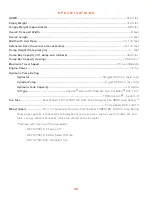
Page 42: ...der Pump 6 gpm 2250 psi Cyl only Hydraulic Tank Capacity 15 Gallon Oil Type Chevron Rando HD Prem MV Hyd Oil Mobil DTE 12 or 12Mor Castrol Aerial Lift Tire Size Rear Wheels LT315 75R16 E Nitto Dune Grappler Tire 3860 Load Rating Front wheels 20 5 x 8 10 Wheel Rear 16 x 10 Aluminum Procomp Part Number 10696182 3420 lb Load Rating Dump box capacity is reduced by the weight of any accessories such as...

Page 43: ...necting on level ground is not possible use blocking in front of and behind rear wheels to prevent the machine from rolling Trailer Connect Position trailer hitch over tow vehicle ball Fasten safety chains Engage parking brake Raise front wheels to lower hitch onto ball Confirm front wheels are in locked position Slightly engage the reverse drive lever to ensure the hydraulic motor has disengaged ...

Page 44: ...e forward or reverse with the drive lever Steer using the marked lever When not moving equipment engage parking brake Dump Box Operation Park Equipter on firm level surface Level equipment with outriggers before raising or extending the dump box Open lids Move dump box into desired position with appropriate levers Keep all outriggers firmly on ground until box is in transport position Never adjust...

Page 45: ......

Page 46: ...855 378 4783 www equipter com 49 Eagle Drive Leola PA 17540 ...

Reviews: