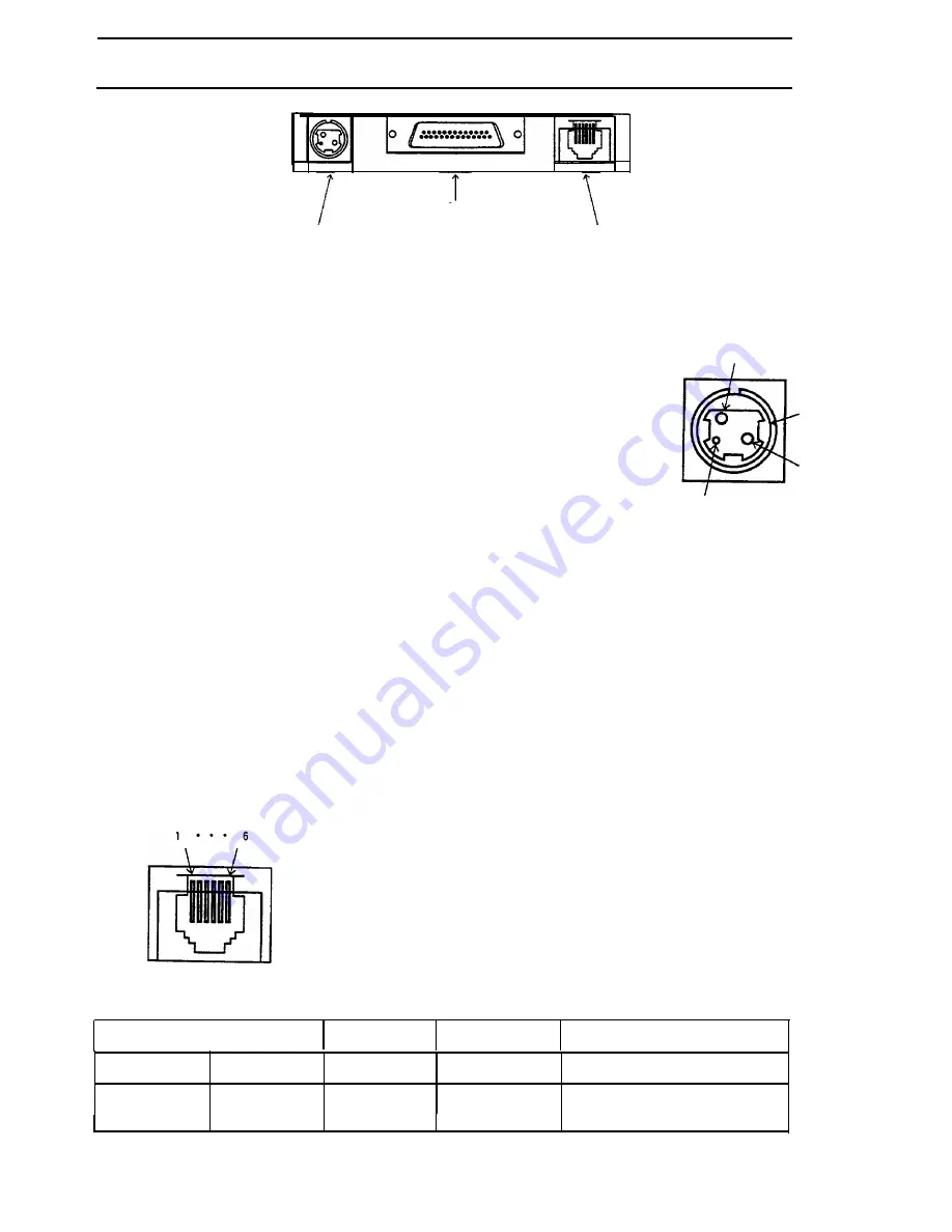
APPENDIX B Connectors
1. Connectors
Serial Interface Connector
Power
Supply Connector
Drawer Kick-out
Connector
2. Interface connectors
See APPENDIX C Interfaces
3. Power supply connector
This connector is used to connect an external power source.
1)
Pin assignment:
Pin
1:
+24
VDC
Pin 2:
GND
Pin 3:
Unconnected
2
S H E L L
1
3
SHELL:
Connected to the frame ground
(FG) at
the
printer side.
2) Model: User side:
Connector:
TCP8927-63-1110
(Hoshiden or equivalent)
Cable:
2-core shielded (AWG22 X 2)
Printer side: TCS7960-53-2010 (Hoshiden or equivalent)
NOTE:
Start the external power supply after connecting the external power
supply.
4. Drawer kick-out connector (Modular connector)
1) Pin assignment:
Printer side connector:
TM5RJ3-66 (HIROSE) or
equivalent
User-side plug:
Standard 6-pin modular jack
(R11 Telephone jack)
Table B-l. Drawer Kick-out Connector Pin Assignment
Pin Number Signal Name
Sender
Connected to:
Function
1
FG
-
Cash drawer
Frame ground
2
L1 (-)
Printer
Cash drawer
Drawer kick-out drive signal
L1.
65
Summary of Contents for TM-L60
Page 1: ...thermal line printer T M L 6 0 Operator s Manual 400179501 ...
Page 7: ...1 SETTING UP ...
Page 21: ...II REFERENCE ...
Page 75: ......
Page 76: ......


