


Troubleshooting
3.5 I/F Related Troubleshooting
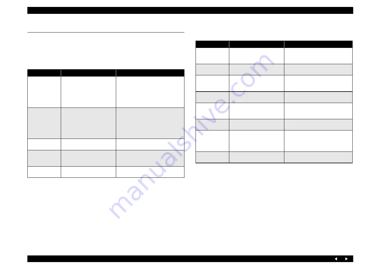
This section describes the troubleshooting for the USB I/F and Memory Card Slot.
USB I/F error
Troubleshooting for Memory Card Slot
Table 3-13. USB I/F Error
Cause
Check Point
Remedy
Host PC does not
support Windows
98 essentially.
On Windows, open “My
computer”
→
“Property”
→
“Device manager”.
“Universal serial bus controller”
is effective?
Remove the USB driver, and install it
again.
Printer driver is not
installed correctly.
On Windows, open “My
computer”
→
“Property”
→
“Device manager”.
Printer driver is not installed in
“Other devices”?
Delete the driver and install it again
according to operation manual.
Defective USB
cable
Operation is normal if USB
cable is replaced?
Replace the USB cable.
Poor contact
Check to see if there is no
adhesion of foreign matters in
the USB interface connector.
Remove the foreign matters, and clean
the contact.
Defective main
board
Check to see if main board is not
damaged.
Replace the main board.
Table 3-14. Troubleshooting for Memory Card
Cause
Check Point
Remedy
Driver has not been
installed correctly.
Check to see if a memory card is
recognized in the single unit
mode.
Temporarily remove the driver, and then
install it again.
Data has been
destroyed.
Data on card may be destroyed
owing to static electricity.
Check to see if card data is read by a PC.
If not, format the card.
A memory card
other than those
specified is used.
Check the card to see if it is one
of the specified cards.
Use a memory card specified.
Memory Card is
faulty.
Check to see if another Memory
Card can be recognized.
Use a new Memory Card.
Poor contact.
Check to see if foreign matters
are not adhering to Memory
Card or slot.
Remove the foreign matters, and clean
the contact.
Firmware has
abnormality.
–
Upload firmware.
Electric noise, etc.
has been
generated.
Check to see if FFC is connected
correctly and Ferrite Core is
positioned in place inside the
printer.
After the confirmation, if they have no
abnormality, replace the main board.
Defective main
board
Check to see if main board is not
damaged.
Replace the main board.
Summary of Contents for Stylus Photo RX700 Series
Page 1: ...EPSON StylusPhotoRX700 Scanner Printer Copier SERVICE MANUAL ECOS SEMF05001 ...
Page 9: ...C H A P T E R 1 PRODUCTDESCRIPTION ...
Page 17: ...C H A P T E R 2 OPERATINGPRINCIPLES ...
Page 51: ...C H A P T E R 3 TROUBLESHOOTING ...
Page 76: ...C H A P T E R 4 DISASSEMBLYANDASSEMBLY ...
Page 133: ...C H A P T E R 5 ADJUSTMENT ...
Page 146: ...C H A P T E R 6 MAINTENANCE ...
Page 163: ...C H A P T E R 7 APPENDIX ...
Page 175: ...Model PM A900 Stylus PHOTO RX700 Board C583Main Sheet 1 3 Rev H ...
Page 176: ...Model PM A900 Stylus PHOTO RX700 Board C583Main Sheet 2 3 Rev H ...
Page 177: ...Model PM A900 Stylus PHOTO RX700 Board C583Main Sheet 3 3 Rev H ...
Page 178: ...Model PM A900 Stylus PHOTO RX700 Board C583 PNL PNL B Sheet 1 1 Rev C ...
Page 179: ...Model PM A900 Stylus PHOTO RX700 Board C583PSB Sheet 1 1 Rev H ...
Page 180: ...Model PM A900 Stylus PHOTO RX700 Board C583PSE Sheet 1 1 Rev F ...


