


EPSON Stylus Photo 750
Revision A
Disassembly and Assembly
Disassembly
55
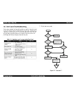
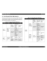
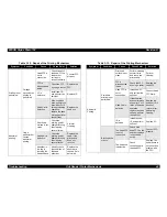
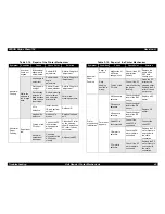
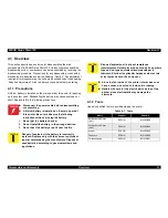
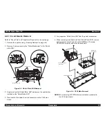
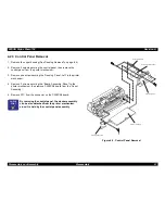
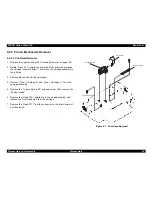
4.2.2 Circuit Boards Removal
Refer to “Check Point” and “Adjustment Required” on the next page.
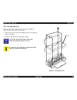
1. Remove the upper housing. (“Housing Removal” on page -54)
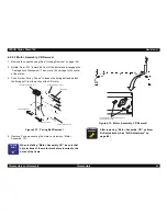
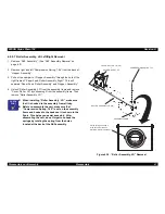
2. Remove 5 screws securing the “Printer Mechanism” to the “Shield
plate, M/B”.
Figure 4-3. Shield Plate, M/B Removal
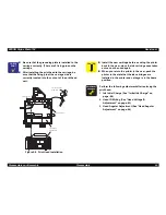
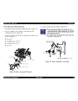
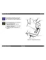
3. Slightly pull out the “Shield Plate, M/B” and remove the cable holder
installed on the “Shield Plate, M/B”.
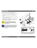
4. Disconnect all the cables from the connectors on the C259 main
board.
5. Fully separate “Shield Plate, M/B” from the printer mechanism.
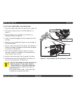
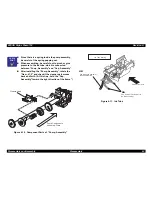
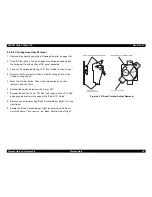
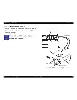
6. When removing each board unit from “Shield Plate, M/B”, remove
each screw securing the each board (C259Main: 10 screws,
C257PSB: 4 screws), and remove each board.
Figure 4-4. C259 Main Removal
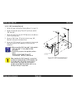
NOTE: When removing C257PSB, disconnect cables connected to
the C259 main board.
[ C a b l e H o l d e r s ]
S H I E L D P L A T E , M / B
M A I N B o a r d
( C 2 5 9 M A I N )
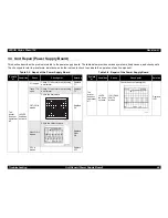
P o w e r S u p p l y B o a r d
( C 2 5 7 P S B )
S H I E L D P L A T E , M / B
Summary of Contents for Stylus Photo 750
Page 1: ...EPSON Stylus Photo750 Color Inkjet Printer SEIJ98005 6 59 0 18 6 59 0 18 6 59 0 18 6 59 0 18 ...
Page 8: ... 3 7 5 4 PRODUCTDESCRIPTION ...
Page 32: ... 3 7 5 5 OPERATINGPRINCIPLES ...
Page 43: ... 3 7 5 6 TROUBLESHOOTING ...
Page 55: ... 3 7 5 7 DISASSEMBLYANDASSEMBLY ...
Page 81: ... 3 7 5 8 ADJUSTMENT ...
Page 95: ... 3 7 5 9 MAINTENANCE ...
Page 101: ... 3 7 5 APPENDIX ...
Page 111: ......
Page 112: ......
Page 113: ......
Page 114: ......


