


EPSON PowerLite 5000 Service Manual
4-3
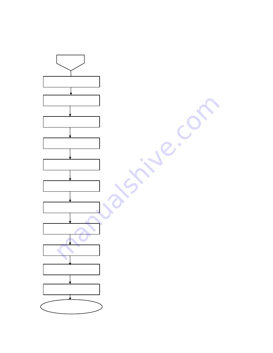
Upper Case Unit
Control Panel
Rear Case Unit
Projector Lens Unit
Lower Case Unit
Air Filter Frame
Lamp Cover
Lamp Inner Housing
Foot Adjusters A and B
Interface Connectors
AC Inlet
Attach the air filter frame, lamp
inner housing and lamp cover.
Start
External View
Turn off the power and remove power and interface cables. Then
check the following:
•
There are no cracks or other deformities.
•
The upper case is secured to the lower case with screws.
(Refer to 3.2.3.)
•
Dirt is not on the front or rear receptor windows of the upper case.
•
Buttons move smoothly.
•
The control panel is mounted on the upper case with 4 tabs.
•
There are no cracks or other deformities.
•
The focus ring and zoom ring are adjustable (move easily).
•
Dirt is not on the lens surface.
•
There are no cracks or other deformities.
•
The mounting screw on the air filter frame is not loose.
•
The tab on the air filter frame is not damaged.
•
Dirt is not on the air filter frame.
•
Dirt is not on the intake fan. (The intake fan is located under the air filter
frame.)
•
The 2 mounting screws on the lamp cover are not loose.
•
The tab on the lamp cover is not damaged.
•
Deformities or discoloration are not present on the lamp inner housing
frame or power cable connector.
•
Damage or dirt is not present on the reflector and surroundings.
•
Foot adjusters A and B should move smoothly.
•
No discoloration or deformities are present on the interface connector.
(Rust may cause discoloration.)
•
Any damage or dirt is not present on the socket.
•
Discoloration is not present on the connector terminal.
•
No damage or dirt is present on the socket.
Figure 4-2
Summary of Contents for PowerLite 5000
Page 1: ...SM ELP 5000 Service Manual Epson America Inc ...
Page 2: ...ii PowerLite 5000 Service Manual ...
Page 112: ...EPSON PowerLite 5000 Service Manual A 4 A 2 Exploded Diagrams Figure A 1 ...
Page 113: ...EPSON PowerLite 5000 Service Manual A 5 Figure A 2 ...
Page 114: ...EPSON PowerLite 5000 Service Manual A 6 Figure A 3 ...
Page 115: ...EPSON PowerLite 5000 Service Manual A 7 Figure A 4 ...
Page 116: ...EPSON PowerLite 5000 Service Manual A 8 Figure A 5 ...
Page 117: ...EPSON PowerLite 5000 Service Manual A 9 Figure A 6 ...
Page 118: ...EPSON PowerLite 5000 Service Manual A 10 Figure A 7 ...
Page 119: ...EPSON PowerLite 5000 Service Manual A 11 Figure A 8 ...
Page 120: ...EPSON PowerLite 5000 Service Manual A 12 Figure A 10 ...
Page 121: ...EPSON PowerLite 5000 Service Manual A 13 Figure A 11 ...
Page 122: ...EPSON PowerLite 5000 Service Manual A 14 Figure A 12 ...
Page 123: ...EPSON PowerLite 5000 Service Manual A 15 Figure A 13 ...
Page 124: ...EPSON PowerLite 5000 Service Manual A 16 Figure A 14 ...
Page 125: ...EPSON PowerLite 5000 Service Manual A 17 Figure A 14 ...
Page 126: ...EPSON PowerLite 5000 Service Manual A 18 Figure A 15 ...
Page 127: ...EPSON PowerLite 5000 Service Manual A 19 Figure A 16 ...


