


EPSON PowerLite 5000 Service Manual
2-18
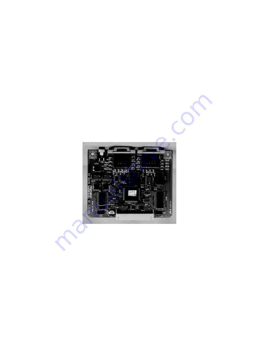
2.7 FR BOARD
The FR board is used for connecting the remote control receiver and a mouse or serial
interface of a host computer. The control has an 8-bit CPU and mouse / serial switching
circuit installed on the board.
CN100 (Mouse / COM1) and CN102 (Mouse / COM2) are multi-mouse connectors. If the
ELP communication kit is installed on the host computer and cables are connected to it,
you can control the computer with the remote control. The controller on the FR board
automatically determines the circuit operation mode (Mouse or Com) to apply the proper
circuit.
The optional remote control receiver can be connected to the remote control interface
(J100). The receiver provides the same functions as the standard receptor board
(FI / RI). Without the receiver, the remote control can be used within a limited area in the
front and rear. The receiver expands the range for the remote control.
Figure 2-15
The signals from the receptor board (FI/RI board) and the optional remote control receiver
are accepted by the remote (IC101), the infrared signals received from the remote control
are output under OR conditions to the main board through CN101 and the connector
board.
If a host computer with the ELP communication kit 2 option is connected to the interface,
the relay circuit is switched depending on each operation. This enables the switch data
transmission to the host computer and remote mouse operation by the remote control.
Summary of Contents for PowerLite 5000
Page 1: ...SM ELP 5000 Service Manual Epson America Inc ...
Page 2: ...ii PowerLite 5000 Service Manual ...
Page 112: ...EPSON PowerLite 5000 Service Manual A 4 A 2 Exploded Diagrams Figure A 1 ...
Page 113: ...EPSON PowerLite 5000 Service Manual A 5 Figure A 2 ...
Page 114: ...EPSON PowerLite 5000 Service Manual A 6 Figure A 3 ...
Page 115: ...EPSON PowerLite 5000 Service Manual A 7 Figure A 4 ...
Page 116: ...EPSON PowerLite 5000 Service Manual A 8 Figure A 5 ...
Page 117: ...EPSON PowerLite 5000 Service Manual A 9 Figure A 6 ...
Page 118: ...EPSON PowerLite 5000 Service Manual A 10 Figure A 7 ...
Page 119: ...EPSON PowerLite 5000 Service Manual A 11 Figure A 8 ...
Page 120: ...EPSON PowerLite 5000 Service Manual A 12 Figure A 10 ...
Page 121: ...EPSON PowerLite 5000 Service Manual A 13 Figure A 11 ...
Page 122: ...EPSON PowerLite 5000 Service Manual A 14 Figure A 12 ...
Page 123: ...EPSON PowerLite 5000 Service Manual A 15 Figure A 13 ...
Page 124: ...EPSON PowerLite 5000 Service Manual A 16 Figure A 14 ...
Page 125: ...EPSON PowerLite 5000 Service Manual A 17 Figure A 14 ...
Page 126: ...EPSON PowerLite 5000 Service Manual A 18 Figure A 15 ...
Page 127: ...EPSON PowerLite 5000 Service Manual A 19 Figure A 16 ...


