background image

6.

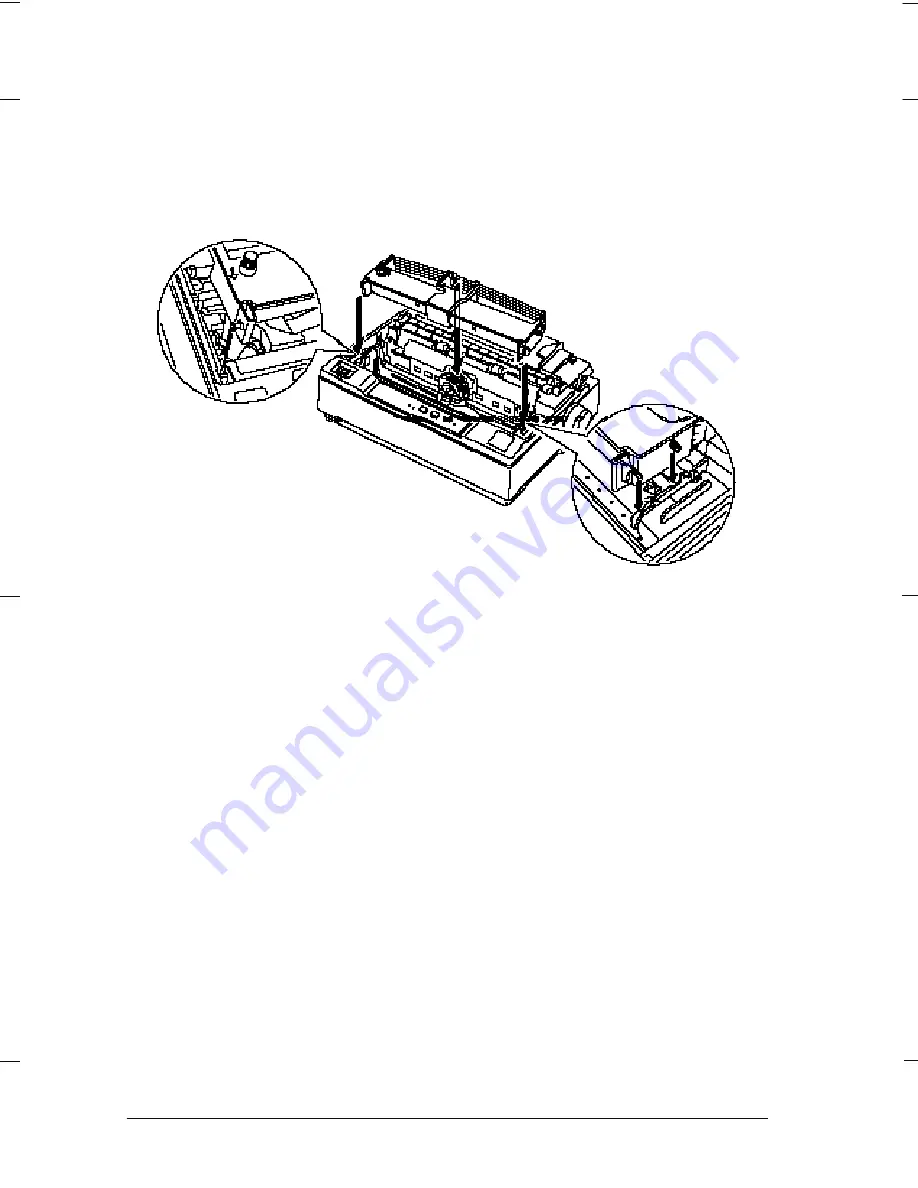
Insérez la cartouche dans l’imprimante conformément à l’illustration
ci-dessous et appuyez fermement à chacune de ses extrémités
pour la mettre en place dans les dispositifs de fixation en matière
plastique.

7.

Tournez le bouton de tension du ruban afin de faciliter la mise en
place du ruban. Vérifiez que le ruban n’est pas plissé ou vrillé.

8.

Remettez le capot en place.

Une fois le ruban couleur en place, lancez le test automatique en
suivant la provédure décrite à la page 1-10.

L

Blackberry REV.C

A5 size

Chapter 2

94/04/26

2-38      

Utilisation de l’imprimante

Summary of Contents for DLQ-3000+

Page 1: ...EPSON EPSON EPSON France S A SERVICE MANUAL DLQ 3000 PRODUIT ...

Page 2: ...EPSON 24 PIN DOT MATRIX PRINTER EPSON DLQ 3000 SERVICE MANUAL SEIKO EPSON CORPORATION 4008259 ...

Page 3: ...al However should any errors be detected SEIKO EPSON would greatly appreciate being informed of them The above notwithstanding SEIKO EPSON can assume no responsibility for any errors in this manual or the consequences thereof EPSON is a registered trademark of SEIKO EPSON CORPORATION General Notice Other product names used herein are for identification purposes only and may be trademarks or regist...

Page 4: ...ANUAL DO NOT CONNECT THE UNIT TO A POWER SOURCE UNTIL INSTRUCTED TO DO SO WHEN THE POWER SUPPLY CABLE MUST BE CONNECTED USE EXTREME CAUTION IN WORKING ON POWER SUPPLY AND OTHER ELECTRONIC COMPONENTS CAUTION 1 REPAIRS ON EPSON PRODUCT SHOULD BE PERFORMED ONLY BY EPSON CERTIFIED REPAIR TECHNICIAN 2 MAKE CERTAIN THAT THE SOURCE VOLTAGE IS THE SAME AS THE RATED VOLTAGE LISTED ON THE SERIAL NUMBER RATI...

Page 5: ...ts of the printer CHAPTER 2 OPERATING PRINCIPLES Describes the theory of printer operation CHAPTER 3 DISASSEMBLY AND ASSEMBLY Includes a step by step guide for product disassembly and assembly CHAPTER 4 ADJUSTMENT Includes a step by step guide for adjustment CHAPTER 5 TROUBLESHOOTING Provides EPSON approved techniques for troubleshooting CHAPTER 6 MAINTENANCE Describes preventive maintenance techn...

Page 6: ...v REVISION SHEET Revision Issued Data Contents Rev A August 21 1997 First Release ...

Page 7: ...vi TABLE OF CONTENTS CHAPTER 1 GENERAL DESCRIPTION CHAPTER 2 OPERATING PRINCIPLES CHAPTER 3 DISASSEMBLY AND ASSEMBLY CHAPTER 4 ADJUSTMENT CHAPTER 5 TROUBLESHOOTING CHAPTER 6 MAINTENANCE APPENDIX ...

Page 8: ... 3 2 7 Control Codes 1 9 1 3 3 Paper Feed Specification 1 10 1 3 3 1 Friction Feed Cut sheet 1 10 1 3 3 2 Tractor Feed Continuous paper 1 10 1 3 3 3 Paper Feed Speed and Accuracy 1 10 1 3 4 Paper Specification 1 11 1 3 5 Printable Area 1 17 1 3 6 Paper Thickness Detection 1 24 1 3 7 Ribbon Cartridge 1 25 1 3 7 1 Monochrome ribbon cartridge 1 25 1 3 7 2 Color ribbon cartridge 1 25 1 3 8 Input Data ...

Page 9: ...nd LCD LED Indicator Conditions 1 39 1 5 1 3 Printer Status and Buzzer 1 40 1 5 2 SelecType 1 41 1 5 2 1 SelecType Phase 1 41 1 5 2 2 SelecType Operation 1 42 1 5 2 3 SelecType Option 1 43 1 5 3 Functions at Power On 1 45 1 5 4 Bi D Adjustment Mode 1 46 1 5 5 Program Reload Mode 1 46 1 5 6 Initialization 1 47 1 5 6 1 Printer Initialization 1 47 1 5 6 2 Initialize Defaults to the Standard 1 48 1 6 ...

Page 10: ...in the copy mode Wide printable area 70 line A4 0 mm can be set for the top and bottom margins at single print mode Paper thickness detection function supported Enables the auto and manual platen gap adjustment Fonts Bitmap fonts 9 LQ and 1 draft typefaces Scalable fonts 4 typefaces Bar code fonts 8 typefaces Character tables Standard version 11 tables NLSP version 30 tables Control codes ESC P2 I...

Page 11: ...il Right Guide Edge Right Guide Edge Lock Printhead Front Paper Guide Left Guide Edge Left Guide Edge Lock Power Switch Paper Thickness Adjust Lever Ribbon Cartridge Paper Support Release Lever Tractor Unit Parallel Interface Serial Interface Figure 1 1 Exterior View of DLQ 3000 ...

Page 12: ...ent serial I F card C82310 C82311 32KB intelligent parallel I F card C82312 Localtalk card C82313 32KB IEEE 488 I F card C82314 Coax I F card C82315 Twin Ax I F card C82331 Ethernet I F card C82345 IEEE 1284 parallel I F card C82346 Multi Protocol Ethernet I F card Accessory Equipment Power supply cable 2 Note 1 Asterisk at the end of the part numbers replaces the last digit of the part number whi...

Page 13: ...g with logic seeking Resolution See Table 1 2 Table 1 2 Printing Resolution Printing Mode Horizontal Density Vertical Density Adjacent Dot Print High speed draft 90 dpi 180 dpi No Draft 120 dpi 180 dpi No Draft condensed 240 dpi 180 dpi No LQ 360 dpi 180 dpi No 8 pin bit image 60 80 90 or 120 dpi 60 dpi Yes 120 or 240 dpi 60 dpi No 24 pin bit image 60 90 120 or 180 dpi 180 dpi Yes 360 dpi 180 dpi ...

Page 14: ...ed 17 cpi 206 190 137 68 103 20 cpi 240 222 160 80 120 Raster 360 dpi 10 cpi 20 20 20 20 20 Printing Speed Mode Selection This printer is designed to control the printing speed according to the power supply voltage and printhead temperature When the power supply voltage drops to the limit the printer stops printing then resumes the job at a slower speed to print the remaining data for the line Whe...

Page 15: ...S M o d e 0 M o d e 2 I s p a p e r t h i c k n e s s 0 1 9 m m B l a c k c o l o r p r i n t Y E S M o d e 2 Y E S C o p y 2 m o d e M o d e 3 M o d e 2 M o d e 2 M o d e 2 Y E S M o d e 0 M o d e 1 N O B l a c k c o l o r p r i n t I s p a p e r t h i c k n e s s 0 1 9 m m Y E S Y E S M o d e 0 N O N O N O N O N O N O P D o w n M e a n s t h a t t h e l i n e i s t h e r e p r i n t e d l i n e ...

Page 16: ...sian PC 869 Greek MAZOAWIA Poland Code MJK CSFR ISO 8559 7 Latin Greek ISO Latin 1T Turkish Bulgaria Bulgaria PC 864 Arabic Estonia PC 774 LST 1283 1933 ISO 8859 2 PC 866 LAT Latvian PC 860 Portuguese PC 861 Icelandic PC 865 Nordic PCAPTEC Arabic PC 708 Arabic PC 720 Arabic PCAR864 Arabic Hebrew7 1 Hebrew8 1 PC862 Hebrew 1 Note 1 Theses character tables are not selected in the SelecType mode 1 3 2...

Page 17: ...PSON Prestige EPSON Script EPSON OCR B EPSON Orator EPSON Orator S Epson Script C EPSON Roman EPSON Sans Serif EPSON Roman T EPSON Sans Serif H PC 864 Arabic EPSON Draft EPSON Roman Not supported PC 437 Greek PC 852 East Europe PC 853 Turkish PC 855 Cyrillic PC 857 Turkish PC 866 Russian PC 869 Greek MAZOWIA Poland Code MJK CSFR ISO 8859 7 Latin Greek ISO Latin 1T Turkish Bulgaria Bulgaria Estonia...

Page 18: ...es See Table 1 5 Table 1 5 Character Matrixes Character Horizontal Dots Vertical Dots Draft 10 cpi 12 24 Draft 12 cpi 10 24 Draft 15 cpi 8 16 LQ 10 cpi 36 24 LQ 12 cpi 30 24 LQ 15 cpi 24 16 LQ proportional 48 maximum 24 Notes 1 The character matrixes for high speed draft 10 cpi characters are made from the draft 12 cpi matrixes 2 The character matrixes for 15 cpi character are also used for supers...

Page 19: ...ope align the left sheet edge guide with the marked position 1 3 3 2 Tractor Feed Continuous paper Paper Path Rear entry push tractor feed with paper parking function Notes 1 Set the release lever to TRACTOR 2 Do not perform reverse feed for more than 1 6 inch 3 Set the left and right sheet edge guides to the right and left ends of the front paper guide respectively 1 3 3 3 Paper Feed Speed and Ac...

Page 20: ...lded or crumpled Cut sheet Multi part form Table 1 7 Cut sheet Specification Multi part Form Minimum Maximum Width Manual insertion 3 6 inch 92 mm 16 5 inch 420 mm CSF 3 9 inch 100 mm 16 5 inch 420 mm Length Manual insertion 3 5 inch 92 mm 16 5 inch 420 mm 1 CSF 3 6 inch 92 mm 14 3 inch 364 mm 1 Copies 1 original and 6 copies Thickness 0 0047 inch 0 12 mm 0 021 inch 0 53 mm Weight I sheet of a mul...

Page 21: ... 5 inch 241 mm Length 4 1 inch 105 mm Thickness 0 0063 inch 0 16 mm 0 021 inch 0 52 mm Weight 45 g m 12 lb m 91 g m 24 lb m Quality Bond paper Plain paper Airmail paper without glue at a flap Notes 1 Fold the flap of the envelope inside before loading at CSF or manual insertion 2 Difference in thickness within the same printable area must be 0 0098 inch or less ...

Page 22: ...ss Single sheet 0 0025 inch 0 065 mm 0 047 inch 0 12 mm 1 sheet of multi part form 0 0047 inch 0 12 mm 0 021 inch 0 53 mm Weight Cut sheet 52 3 g m 14 lb 105 g m 27 lb 1 sheet of multi part form 40 g m 11 lb 58 g m 15 lb Quality Plain paper Reclaimed paper Carbon less multi part form Jointing 1 Must be one of the followings Point glue on the both sides Tape staple on the both sides Point glue on o...

Page 23: ...19 mm Label weight 64 g m 17 lb Quality Plain paper or equivalent The base sheet must be continuous paper Notes 1 Use labels in the condition of the room temperature only 2 Labels backed with the continuous base sheet can be used only 3 When the label sheet whose base sheet is exposed around the labels adjust the platen gap manually to the portion covered with the label using PG adjust lever 2 1 2...

Page 24: ...te of less than 60 such as black Continuous forms with labels Table 1 12 Continuous Forms with Labels Specification Minimum Maximum Base sheet width 4 0 inch 16 0 inch 101 6 mm 406 4 mm Base sheet length 4 0 inch 22 0 inch 1 page 101 6 mm 559 mm Total thickness 0 021 inch 0 53 mm Quality Plain paper or equivalent Airmail paper without glue at a flap Note When using the continuous forms with labels...

Page 25: ...ulti part forms with labels Table 1 14 Overlapping Multi Part Form with Labels Specification Minimum Maximum Base sheet width 4 0 inch 16 0 inch 101 6 mm 406 4 mm Base sheet length 4 0 inch 22 0 inch 1 page 101 6 mm 559 mm Total thickness 0 026 inch 0 65 mm Jointing Multi part forms Point glue Joint for the base sheet and multi part form Point glue Note When using overlapping multi part forms with...

Page 26: ... PW Refer to Section 1 3 4 Refer to Section 1 3 4 Paper length PL Refer to Section 1 3 4 Refer to Section 1 3 4 Left margin LM 3 mm 0 118 or more 3 mm 0 118 or more A3 landscape 31 mm 1 22 or more A3 landscape 31 mm 1 22 or more Right margin RM 3 mm 0 118 or more 3 mm 0 118 or more A3 landscape 20 mm 0 78 or more A3 landscape 20 mm 0 78 or more Top margin TM 0 mm 0 or more 0 mm 0 or more Bottom ma...

Page 27: ... 165 or more Bottom margin BM 4 2 mm 0 165 or more Notes 1 In the top 75 mm are the paper feeding pitch may be irregular 2 Forms override printing is available for 2 lines after the paper end is detected Paper feeding pitch is not guaranteed The end of the printable area is 4 2 m or more apart from the bottom edge of the paper 3 When the page width is 16 inches note the followings LM is 18 mm or m...

Page 28: ...ion 1 3 4 Paper length PL Refer to Section 1 3 4 Left margin LM 12 mm 0 472 or more Top margin TM 1 2 mm 0 0472 or more Left margin on label LOL 3 mm 0 118 or more Right margin on label ROL 3 mm 0 118 or more Top margin on label TOL 3 mm 0 118 or more Bottom margin on label BOL 3 mm 0 118 or more Notes 1 Do not feed paper backward 2 Use only the specified paper path for continuous paper 3 The pape...

Page 29: ...a l i n s e r t i o n f o r m t h e f r o n t Figure 1 10 Printable Area for Envelopes Table 1 17 Printable Area for Envelops Continuous paper Paper width PW Refer to Section 1 3 4 Paper length PL Refer to Section 1 3 4 Left margin LM 3 mm 0 118 or more Right margin RM 3 mm 0 118 or more Top margin TM 0 mm 0 or more 1 Bottom margin BM 0 mm 0 or more Note 1 At CSF insertion 4 2 mm 0 16 or more ...

Page 30: ...8 or more Right margin RM 19 mm 0 748 or more Top margin TM 21 2 mm 0 835 or more Bottom margin BM 4 2 mm 0 165 or more Left margin from the multi part form to the base sheet LMB 13 mm 0 512 3 mm 0 118 Right margin from the multi part form to the base sheet RMB 13 mm 0 512 3 mm 0 118 Notes 1 Do not feed paper backward 2 Use only the specified paper path for continuous paper 3 The paper feeding pit...

Page 31: ...2 mm 0 165 or more Left margin for label LFL 45 mm 1 77 or more Right margin from label RFL 45 mm 1 77 or more Top margin from label TFL 25 mm 0 984 or more Bottom margin from label BFL 25 mm 0 984 or more Left margin on label LOL 3 mm 0 118 or more Right margin on label ROL 3 mm 0 118 or more Top margin on label TOL 3 mm 0 118 or more Bottom margin on label BOL 3 mm 0 118 or more Notes 1 Do not f...

Page 32: ... 0 748 or more Left margin from the multi part forms to the base sheet LMB 13 mm 0 552 3 mm 0 118 Right margin from the multi part forms to the base sheet RMB 13 mm 0 552 3 mm 0 118 Top margin TM 21 2 mm 0 835 or more Bottom margin BM 4 2 mm 0 165 or more Non printable area NA 25 4 mm 1 0 or more Left margin from label LFL 45 mm 1 77 or more Right margin from label RFL 45 mm 1 77 or more Top margi...

Page 33: ...onding paper thickness and platen gap Table 1 21 PG Adjust Lever Adjust lever Paper thickness inch Paper thickness mm PG position Maximum Minimum Maximum Minimum Inch mm 1 0 0024 0 0043 0 06 0 11 0 0138 0 35 0 0 0024 0 0043 0 06 0 11 0 0154 0 39 1 0 0043 0 0059 0 11 0 15 0 0169 0 43 2 0 0059 0 0075 0 15 0 19 0 0181 0 46 3 0 0075 0 0098 0 19 0 25 0 0197 0 50 4 0 0098 0 0122 0 25 0 30 0 0217 0 55 5 ...

Page 34: ...Item No S015066 At 10 cpi printing in the LQ mode 48 dots per character 1 3 7 2 Color ribbon cartridge Color Black Magenta Cyan Yellow Ribbon fabric Nylon 66 Ribbon dimension 25 5 mm W X 17 mm L X 1 5 mm D ribbon thickness 0 128 mm 0 007 mm Cartridge dimension 153 mm 6 0 W X 33 mm 1 3 H X 105 mm 4 1 D Ribbon life Black 1 5 million characters Magenta 1 1 million characters Cyan 1 1 million characte...

Page 35: ... Input voltage range AC 198 to 264 V Rated frequency renege 50 to 60 Hz Input frequency range 49 5 to 60 5 Hz Rated current 0 7 A maximum Power consumption Approximately 60 W ISO IEC 10561 Letter pattern Energy Star program compliant Insulation resistance 10 M ohms min Between AC line and chassis DC 500 V Dielectric strength AC 1 500 Vrms For 1 minute Between AC line and chassis 1 3 10 Safety Appr...

Page 36: ... characters Yellow 0 8 million characters 1 character is formed with 48 dots At 10 cpi printing LQ mode 1 3 14 Environmental Conditions Table 1 22 Environmental Condition Operating Non operating 5 to 35 C 30 to 65 C Temperature 15 to 35 C 1 20 to 40 C 1 15 to 25 C 2 10 to 80 5 to 85 Humidity 3 10 to 80 1 5 to 85 1 20 to 60 2 Resistance to shock 0 25G 10 to 55 Hz Directions X Y and Z 0 50G 10 to 55...

Page 37: ...4 V IOL 12 mA VOL 0 4 V CO 50 pf VIH 2 0 V VIL 0 8 V IIH 0 32 mA VIH 2 0 V IIL 12 mA VIL 0 8 V CI 50 pf A LOW logic level on the Logic H signal is as follows 2 0 V or less when the printer is powered off 3 0 V or more when the printer is powered on The receiver provides an impedance equivalent to 7 5 K ohms to ground The BUSY signal is HIGH in the following cases During data entry When the input d...

Page 38: ... treply tack 500 ns 10 s tnbusy 0 tnext 0 tt out 1 120 ns tt in 2 200 ns Note 1 Rise and fall time for output signals 2 Rise and fall time for input signal S T O R B E D A T A n D A T A D A T A n 1 A C K N L G B U S Y t h o l d t s e t u p t s t b t r e a d y t b u s y t r e p l y t a c k t n b u s y t n e x t Figure 1 14 Data Transmission Timing Chart ...

Page 39: ...t data 11 BUSY 29 O When this signal is at a HIGH level the printer is not ready to accept data 12 PE 28 O When this signal is at a HIGH level the paper empty status is detected 13 SLCT 28 O Always at a HIGH level when the printer is powered on 14 AFXT 30 I Not used 31 INIT 30 I The falling edge of a negative pulse or a LOW signal on this line causes the printer to initialize Minimum 50 us pulse i...

Page 40: ...gnal is High when the data is logical 1 and LOW when the data is logical 0 10 PtrClk 28 O Clock signal from the printer 11 PtrBusy Data bit 3 7 29 O Busy signal from the printer Data bit 3 or 7 in reverse channel 12 AckDatareq Data Bit 2 6 28 O Acknowledge request signal Data bit 2 or 6 in reverse channel 13 Xflag Data bit 1 5 28 O X flag signal Data bit 1 or 5 in reverse channel 14 HostBusy 30 I ...

Page 41: ...sibility request values are 00H or 04H as follows 00H Request nibble mode reverse channel transfer 04H Request device ID using nibble mode rev channel transfer Device ID The printer sends following device ID string upon request 00H 3DH MFG EPSON CMD ESCPL2 PRPXL24 BDC MDL DLQ 3000 CLS PRINTER ...

Page 42: ... DTR signal is SPACE and XON code DC1 11H is transmitted when the rest of the input buffer becomes 256 byte Error handling Parity error is detected only Overrun error and framing error are ignored Connector 25 pin sub miniature D shell connector female Table 1 27 Connector Pin Assignment for Serial Interface Pin No Signal Name I O Function Description 1 Chassis GND Chassis GND 2 TXD Out Transmits ...

Page 43: ...rt Hard Ware Reset Accept Execute OK 02h Start Soft Ware Reset Reject 03h Send Main System Type Accept Execute OK 04h Send Name Data Reject 05h Inquire Name Data Accept Execute OK 06h Send Product Name Accept Execute OK 07h Send Soft Ware Emulation Type Accept Execute OK 08h Complete Buffered Data Accept Execute OK 09h Stop Procedure Reject 0Ah Return Buffered Data Reject 0Bh Send Entity Type Acce...

Page 44: ...pe Deciding the level of type B I F after power on 04h Send Name Data Type B I F option command 05h 07h Inquire Software Emulation Name Changing software Emulation Type 0Eh Inquire ASCII Message Writing to DBIN register 14h Inquire Emergency Reply Reply for Emergency command 15h Send Emergency Message Receive Emergency Command Emergency Command Table 1 31 Emergency Command Command No Command name ...

Page 45: ... data first is selected When the host stops data transfer and the printer is in stand by state for the seconds specified by SelecType the printer is returned to the idle state As long as the host sends data or the printer interface is busy state the selected interface is left as it is Interface selection and interface state Interface selection and the corresponding interface states are as follows ...

Page 46: ...ear off LED Orange Pause LED Orange 1 5 1 1 Button Operations Effectiveness Basically all button operations are always effective except for the following cases During printing only the Pause button is effective The SelecType button is only effective during the printer is in the standby status Load Eject and Pause buttons are not effective during the SelecType mode Pause functions Press the Pause b...

Page 47: ... is remaining in the buffer the printer goes into a paper out error state at each end of a sheet and waits for the next sheet to be inserted CSF insertion is enabled again by loading sheets into the CSF or by initializing the printer 3 and buttons are used as described below Pressing the button continuously feeds paper forward backward with a increment of 1 180 inch Pressing the button continuousl...

Page 48: ...e paper Off On Off 6 On 13 Data is in buffer but the printer is paused Data in Buffer Off On Off 14 Pause Pause 0 Off On Off 15 Bi D adjustment Bi d adjustment Off Off Off 15 Hex dump mode Hex dump Off Off Off 15 Ordinary printing Printing 0 Off Off Off 15 Test printing Test Printing Off Off Off 15 Setting printing Setting Printing Off Off Off 16 Standby Ready 0 Off Off Off Notes 1 Fatal error occ...

Page 49: ...nter Status and Buzzer Printer status Beeper sound Paper out error has occurred Paper size error has occurred Incomplete changing paper path error Eject error has occurred Release lever operation error has occurred Paper jam error has occurred Fatal error has occurred Illegal operation in SelecType Notes The symbols and represent how a beep sounds Sounds 100 ms with the interval of 100 ms Sounds 5...

Page 50: ... t a n d b y s t a t e S e l e c T y p e P I T C H S e l e c T y p e 1 p h a s e F O N T F o n t s e l e c t i o n p h a s e P i t c h s e l e c t i o n p h a s e S e l e c T y p e S e l e c T y p e S e l e c T y p e S e l e c T y p e 2 p h a s e S e l e c T y p e D a t a s a v e p h a s e i n i t n a l i z a t i o n S e l e c T y p e P r i n t e r S t a t e S e l e c T y p e P h a s e E n t r y t...

Page 51: ...e SelecType button to exit the SelecType phase With this operation new settings are automatically stored in the EEPROM and are effective until they are changed again This process is automatically followed by the SelecType initialization phase and the printer returns to the stand by status Initializing all settings to the standard Select Standard Setting in the SelecType 2 menu The message Ready is...

Page 52: ... PC869 ISO Latin 1T Code MJK Bulgaria Estonia ISO 8859 7 MAZOWIA PC774 ISO 8859 2 PC866LAT PCAPTEC PC 708 PC720 PCAR864 PC 860 PC865 PC861 USA KOREA Standard version PC437 PC850 PC860 PC861 PC863 PC865 Abicomp BRASCII ISO Latin 1 Roman 8 U S A Korea Page Tractor 11 inch 12 inch 8 5 inch 70 6 inch A4 Other See the right column Option for Other xxx lines from 24 to 132 lines at 1 6 line spacing Page...

Page 53: ...BM 2391 Plus Auto CR IBM Off On For emulation A G M IBM Off On For emulation Interface Auto Selection Parallel RS 232C Option Slot I F Time out 10 sec From 1 to 255 seconds Input Buffer On Off Baud Rate 300 BPS 600 BPS 1200 BPS 2400 BPS 4800 BPS 9600 BPS 19200 BPS Parity None Even Odd Auto Tear off Off On Auto LF Off On 0 Slash Off On Buzzer On Off Standard Setting Ready Font Roman Sans Serif Cour...

Page 54: ... menu along with their options are printed with the subtitles in the selected language Exit When the printing is complete the printed sheet or continuous paper is ejected or fed to the tear off position respectively Then the printer returns to the standby status Interface State All the interfaces keeps a busy state during the printing Note In each mode mentioned above when the printer fails to loa...

Page 55: ... f f P r e s s o r b u t t o n u n t i l t h e L C D i n d i c a t e s t h e n u m b e r f o r t h e m o s t c l o s e l y a l i g n e d p a t t e r n F i x t h e s e l e c t e d n u m b e r b y p r e s s i n g b u t t o n a n d t h e p r i n t e r p r i n t s t h e n e x t p a t t e r n p r i n t E n d A r e a l l t h e a d j u s t m e n t s m a d e N e x t P r e v i o u s E n t e r Figure 1 18 B...

Page 56: ... Initialization Trigger The printer recognizes the INIT signal negative pulse of parallel interface Actions Performed Clears input data buffer Clears download character set Clears print buffer Sets default values Initialization by the control panel operation Trigger Pressing the Pause and Load Eject buttons for 3 seconds Actions performed Clears input data buffer Clears print buffer Sets default v...

Page 57: ...acing 1 6 inch Top Margin Tractor 8 5 mm Manual Rear 8 5 mm Manual Front 8 5 mm CSF 8 5 mm Bottom Margin Tractor 0 0 mm Left Margin 0 column Right Margin 136 columns Print Direction Bi directional Message Language English Software ESC P2 Interface Auto Selection Interface Auto Selection Time out 10 seconds Input buffer ON Serial interface Baud Rate 19200 bps Parity None Auto Tear off Off Auto LF O...

Page 58: ...ay E05B46 CG ROM DRAM EEPROM Drivers Flash ROM P ROM for the program ROM H 8 3 0 0 3 C P U E 0 5 A 8 8 G A T E A R R A Y F l u s h R O M P R O G R A M D R A M M P 5 3 0 2 R i b b o n M o t o r D r i v e r S L A 7 0 2 6 M C R M o t o r D r i v e r S L A 5 0 0 1 P r i n t h e a d D r i v e r 2 S A 1 4 5 1 P r i n t h e a d D r i v e r C G R O M S L A 7 0 2 4 M P F M o t o r D r i v e r S D C 0 3 V 1...

Page 59: ...E T F i l t e r T L 4 9 4 R e g u l a t o r T r a n s f o r m e r T 1 0 1 T r a n s f o r m e r T 2 0 1 Figure 1 20 C124PSB PSE Board Component Layout 1 6 3 Printer Mechanism The printer mechanism of this printer is composed of the followings CR motor PF motor Ribbon motor PG motor 2 cooling fans Paper feed mechanism CR mechanism Figure 1 21 Printer Mechanism ...

Page 60: ... assembly Rear shield cover Printer cover assembly Rear cover Upper connector cover U p p e r H o u s i n g A s s e m b l y R e a r S h i e l d C o v e r U p p e r C o n n e c t o r C o v e r P r i n t e r C o v e r A s s e m b l y L o w e r H o u s i n g A s s e m b l y R e a r C o v e r B o t t o m F r a m e A s s e m b l y Figure 1 22 Printer Housings ...

Page 61: ...cuit Operating Principles 2 13 2 2 1 Power Supply Voltage 2 13 2 2 2 Power Supply Circuit Operation 2 14 2 3 Controller Circuit 2 15 2 3 1 Interface Circuit 2 17 2 3 2 Reset Circuit 2 18 2 3 3 Memory Back up Circuit 2 19 2 3 4 Ribbon Motor Controller Driver Circuit 2 20 2 3 5 PF Paper Feed Motor Controller Driver Circuit 2 21 2 3 6 CR Carriage Motor Controller Driver Circuit 2 22 2 3 6 1 Bi D Adju...

Page 62: ...2 3 12 Other Sensor Circuits 2 30 ...

Page 63: ... actuating plate which joins to the dot wire This movement rushes the wire toward the platen 3 When the dot causes impact to the platen it presses the ribbon to the paper where a dot prints 4 When the coil energizing is terminated the iron core losing magnetic force is returned to the standby position by the bounce of the platen and tension of the actuating spring The printing mechanism has an int...

Page 64: ... 200 million strokes wire Color ribbon 100 million strokes wire Weight 180 g Coil resistance 8 19 0 5 at 25 C Response period Normal mode 462 s Drive voltage 31 5 to 38 5 V Driving condition Normal drive copy mode when multi part form or thick paper is used High duty condition head temperature is high Cold mode head temperature is low Environmental condition Temperature 5 to 55 C Humidity 10 to 85...

Page 65: ...d on and once it is detected CR movement is put under the open loop control system After the controller circuit determines where to move the CR according to the received data it converts the distance to the position into the corresponding phase change pulse and outputs it to the CR motor If the CR home position is detected during printing or the printer initialization it indicates the status that ...

Page 66: ...sor Platen Figure 2 3 PG adjustment Mechanism The PG adjustment mechanism located at the left top of the printer mechanism unit consists of the PG motor CR guide shaft sectorial gear combination gear PG home position sensor and paper thickness sensor After the PG is determined by the controller circuit according to the paper thickness the PG motor rotates corresponding amount The torque from the P...

Page 67: ... 53 Note 1 Note 2 Note 1 PG width corresponds to the detected paper thickness 2 Copy mode is used for paper with the thickness of 0 2 mm or more Automatic PG adjustment function PG is automatically adjusted based on the paper thickness detected paper thickness sensor which consists of the slit disc and the photo electric transfer Paper thickness is detected in the following order 1 PG home positio...

Page 68: ...refers to the switch mode of the sensor when the printer is turned on or resuming the operation after the cover open error is detected The motor is controlled by the open loop system While the motor is used for the ribbon shift the color home position sensor detects the reference position black to manage the color ribbon shift The motor drive speed and phase excitement mode changes in accordance w...

Page 69: ...s composed of 4 colored bands of black red blue and yellow When the color ribbon cartridge is installed on the CR it is detected by the color HP sensor and the printer enters the color ribbon mode With this mechanism the color print with 7 different colors is enabled The printer shifts the color ribbon cartridge to the black band position before shifting to another color each time the printer is t...

Page 70: ...oring Sequence Print color Print ribbon First print Second print Black Black Magenta Magenta Cyan Cyan Yellow Yellow Green Yellow Cyan Orange Yellow Magenta Violet Magenta Cyan CS Reduction Gear Ribbon Transmission Gear A Ribbon Transmission Gear B Ribbon Planetary Gear Ribbon Motor CS Drive Lever CS Drive Cam Color HP Sensor CS Drive Lever Ribbon Planetary Gear Figure 2 6 Ribbon Shift Gear Train ...

Page 71: ...emoval mode Torque is disengaged from all the rollers in this mode See Section 2 1 5 3 A stepping motor is used for the PF motor which enables the paper to move to and stop at any position regardless of the direction The motor is controlled by the controller circuit by the open loop system It refers to the signals output from the sensors in the mechanism to determine the amount to slide paper and ...

Page 72: ...selected by the CPU depending on the movements of the paper feed and carriage motors Figure 2 8 illustrates the paper feed sensor mechanism Table 2 7 lists the paper feed sensor functions P r i n t h e a d L e f t P E W S e n s o r P l a t e n L e f t P E W S e n s o r P r i n t e h a d P a p e r E j e c t D r i v e R o l l e r A s s e m b l y M a s k G u i d e F r o n t P a p e r S e n s o r R i ...

Page 73: ... paper Detects the leading edge and printable area for the black solid print paper Front paper sensor alone Detects the leading edge of the paper Performs front paper feeding Paper jam sensor Paper jam detection Detects paper jam condition in the front rear paper feed direction Notes 1 When the printer is powered on if any of the right left PEW sensor and front rear paper sensor detects paper the ...

Page 74: ... the tractor gear train to feed continuous paper The sub paper loading rollers are used to hold and feed the paper only Paper jam removal mode To set the release lever to this mode releases the paper bail as well as the sub paper loading rollers In this full release condition the jammed paper can be manually ejected The release sensor detects whether the release mechanism is in the cut sheet mode ...

Page 75: ...ype switching regulator which outputs DC voltage required to operate the printer DC voltage is divided into 3 blocks 35 VDC CH A 35 VDC CH B and 5 VDC as listed below Table 2 9 DC Voltage Application Voltage level Connector No Application 35 VDC 10 CN2 CH A CR motor Printhead drive voltage CH B Printhead Cooling fan motor PF motor Ribbon motor Vpp of the flush memory 5 VDC 5 CN3 Logic Hold voltage...

Page 76: ...w 13 V Q153 Q253 and Q154 are turned on by the detector circuit which consists of the R173 R273 and R174 R274 then the PC102 goes on and the current cuts off as the result At this time the delay circuit which consists of C157 and R154 makes the delay time When the printer is turned on the protection circuit can not start operation since the delay circuit acts to prevent the drivers on the main con...

Page 77: ...f the controller circuit Gate Array E05B46 IC25 Controls systems and peripheral devices Gate Array E05A89 built in the panel circuit board Functions as the I F between the control panel and controller circuit Flash ROM IC15 Stores the control program PROM IC18 Stores the control program when the Flash ROM is not equipped CG 8 Mbit MROM IC21 Character generator CG 4 8 Mbit MROM IC24 Character gener...

Page 78: ...I C C o v e r O p e n S e n s o r C o l o r H P S e n s o r R e a r P a p e r S e n s o r F r o n t P a p e r S e n s o r L e f t R i g h t P E W S e n s o r C R H P S e n s o r R e l e a s e S e n s o r C S F P a p e r Q u a n t i t y S e n s o r C S F S e n s o r P G H P S e n s o r P a p e r J a m S e n s o r 3 5 V S e n s o r C R M o t o r D r i v e r P F M o t o r D r i v e r R i b b o n M o ...

Page 79: ...e input buffer The CPU directly outputs TXD data The codes DC1 DC2 and DC3 are outputs when the input buffer is full and DC1 is output when the buffer memory recovers to the normal level The signal REV same as is output to the port PC0 of the CPU to control the DTR The printer resumes printing when the CR code is received or the input buffer is full Type B interface Type B interface is also contro...

Page 80: ...covers from the reset condition before the CPU and the gate arrays recover from the reset condition RST594E monitors the CPU and the gate arrays The threshold voltage is set at approximately 4 2 VDC The reset signals is kept output until the 5 VDC line is 4 2 VDC Since the reset signal from the RST592D is sent to the manual reset terminal MRST in the RST594E via the output port of the CPU the Flas...

Page 81: ... for the boot strap program The first operation date accumulated print amount accumulated power on time and timing for ribbon replacement Data to be backed up is transferred by the gate array as serial data At printer power off the gate array outputs the chip select signal ESC from port 126 and data to be backed up is sent to the EEPROM from port 124 EDO before the power supply voltage completely ...

Page 82: ...e array While in the color ribbon mode the printer switches mode between the copy mode and normal mode according to the signal output from the paper thickness sensor See Table 2 11 for the ribbon motor drive term Table 2 11 Ribbon Motor Drive Term Motor type 4 phases 48 pole PM type stepping motor Power supply voltage 35 VDC 10 Coil resistance 76 10 at 25 C per phase Drive frequency At color selec...

Page 83: ...ray See Table 2 12 which specifies the PF motor terms Table 2 12 PF Motor Drive Term Motor type 4 phases 200 pole HB type stepping motor Power supply voltage 35 VDC 10 Coil resistance 5 0 10 Drive frequency 1430 7200 pps Driving mode Constant current uni polar drive Excitation mode 1 2 phase 2 2 phase RUSH HOLD Paper feed speed 42 m second 6 IPS intermittent drive Minimum step 0 07 mm 1 360 step C...

Page 84: ... steps with the range of 0 to 100 These 4 steps are divided further into 8 steps which varies depending on the combination with the continuity timing Table 2 13 CR Motor Specification Motor type 4 phases 200 pole HB type stepping motor Power supply voltage 35 VDC 10 31 5 38 5 VDC Coil resistance 1 1 10 at 25 C phase Drive frequency 960 to 5760 pps Consumption current 2 2 phase 4 fold speed 2 5 A p...

Page 85: ...7 On On 8 On Note Applicable when the CR moves from 1st to 136th column direction Table 2 16 W1 2 Phase Drive Step No Phase A Phase A Phase B Phase B 1 On 70 7 On 70 7 2 On 43 1 On 100 3 On 100 4 On 43 1 On 100 5 On 70 7 On 70 7 6 On 100 On 43 1 7 On 100 8 On 100 On 43 1 9 On 70 7 On 70 7 10 On 43 1 On 100 11 On 100 12 On 43 1 On 100 13 On 70 7 On 70 7 14 On 100 On 43 1 15 On 100 16 On 100 On 43 1...

Page 86: ... when the carriage moves from the 1st to 136th column as reference Since print timing pulse varies according to the carriage speed the adjustment should be implemented for each speed mode For this printer the adjustment can be made for the 4 fold 2 fold and the default speeds 2 3 6 2 Interlock Function The mechanical cover open switch is serially connected to the common VPA on the CR motor When th...

Page 87: ...in respond speed at continuous printing V P A V P B 3 1 5 3 8 5 V T P r i n t P u l s e A P r i n t P u l s e B H e a d C o i l H e a d C o i l D r i v e W a v e f o r m P r i n t P u l s e A P r i n t P u l s e B Figure 2 18 Printhead Drive Waveform Data from the host computer is expanded into image data CG data and latched in the gate array E05B46 The head data is allocated in the gate array The...

Page 88: ...n sensor signal on the logic line is directly sent to the main control board via the control panel board If the printer cover is open an interlock switch function is activated for safety and puts the printer inactive state L C D P N L T O M A I N M A I N T O P N L S C K 5 V G N D L E D s R S T D A T A C A S E O P E N L C D D r i v e r G a t e A r r a y E 0 5 A 8 9 S w i t c h C o v e r O p e n S e...

Page 89: ...ame gate array Then the transistors 2SC3859 Q4 and SHA03 V1 Q3 are turned off to change the drive voltage from PBS 35V to the 5 VDC See Table 2 18 for PG motor specification Table 2 18 PG Motor Specification Motor type 4 phases 8 pole PM type stepping motor Power supply voltage 35 VDC 6 Coil resistance 250 18 Consumption current per 1 phase Rush 0 2 A on the average Hold 0 02A Drive frequency 350 ...

Page 90: ...f pulses output while the printhead moves from PG home position to the platen surface and surface of the loaded paper to determine the paper thickness which corresponds to the difference between 2 values The numbers of pulses are counted in the following order 1 After the printer power is turned on the PG home position is detected 2 Distance between the printhead and platen surface is measured Whi...

Page 91: ...er Jam Sensor Block Diagram The CPU reads the signal output directly from the paper jam sensor for each step 1 216 inch step If the current signal condition is the same as the previous one it indicates the status that the magnetized roller is not rotating which is considered paper jam When the printer detects that condition continuously for the specified numbers of the output signals it indicates ...

Page 92: ...r Specification Detecting method Mechanical switch Power supply voltage 5 VDC 5 Detecting mode Cover open LOW Cover closed HIGH Color HP Home Position sensor Color HP sensor uses a photo interrupter system When the home position for the color ribbon cartridge is detected the output signal is pulled up to 10 K then input to the CPU port via the filter circuit which consists of the resistance and th...

Page 93: ...r width so as to determine the right and left margins The output signal is output to the CPU A D converter Table 2 25 Right left PEW Sensor Specification Detecting method Photo micro sensor system Output system Collector Power supply voltage 5 VDC 5 CR home position sensor The output signal for this sensor is pulled up to 10K then input to the CPU A D converter via the filter circuit which consist...

Page 94: ...sensor CSF sensor a potentiometer is not attached to the printer but to the CSF It monitors paper quantity in the hopper and send the analog signal to the internal A D converter of the CPU PGHP Platen Gap Home Position sensor The output signal for this sensor is pulled up to 390 then input to the CPU port via the filter circuit which consists of the resistor and the condenser Table 2 29 PGHP Senso...

Page 95: ...ing Assembly Removal 3 11 3 2 6 Printer Mechanism Removal 3 12 3 2 6 1 Printer Mechanism Removal 3 13 3 2 6 2 HP Home Position Sensor Assembly Removal 3 14 3 2 6 3 Front Paper Sensor Removal 3 14 3 2 6 4 PF Sensor Assembly Removal 3 15 3 2 6 5 PF Motor Assembly Removal 3 15 3 2 6 6 CR Motor Assembly Removal 3 16 3 2 6 7 CS Color Shift Motor Assembly Removal 3 17 3 2 6 8 Paper Eject Lever Assembly ...

Page 96: ...3 2 6 16 Platen Removal 3 26 3 2 6 17 Paper Jam Sensor Rear Paper Sensor Removal 3 28 3 2 7 Lower Housing Assembly Removal 3 29 3 3 Reloading the Control Program 3 30 ...

Page 97: ...ssembling remove all options and accessories such as a sheet guide and a ribbon cartridge 3 1 1 Tools Make sure you use the tools listed in Table 3 1 when disassembling and assembling the printer Table 3 1 Tools Tools Availability Part No Phillips screwdriver 2 Y B743800200 Box driver Y B741700200 Thickness gauge set Y B776702201 Round nosed pliers Y B740400100 Nippers Y B740600100 Tweezers Y B741...

Page 98: ...ting OK Is the CR motor overheated Paper feed mechanism Is paper fed smoothly Is the PF motor overheated Is the platen damaged Paper paths Is paper selection smooth Are tractor teeth OK Is there any foreign matter lodged in the paper paths mechanism Does the PG move smoothly when measuring the PG Is the PG properly set Self test Is the test successful On line test Is the test successful Printhead ...

Page 99: ...rol panel removal 5 Upper housing assembly removal 6 Printer mechanism disassembly Refer to the exploded diagrams in Appendix for detailed part engagement and location Note Perform Control program reload when C210 MAIN and sub boards are replaced E l e c t r i c a l C i r c u i t B o a r d R e m o v a l A d j u s t S w i t c h R e m o v a l P r i n t e r M e c h a n i s m D i s a s s e m b l y L o...

Page 100: ...S 3X12 securing the printhead Step 2 Lift up the printhead a little and release the head FFCs from the clips in the CR assembly Then disconnect the FFCs from the printhead Step 3 Remove the printhead from the CR assembly Head FFC Printhead CBS Screws 3X12 Figure 3 2 Printhead Removal Perform Platen gap adjustment after replacing the printhead When replacing the printhead replace the ribbon mask al...

Page 101: ...ion 3 2 1 1 Step 2 Release the harnesses for the PEW sensors from the cable clamp Step 3 Flip the paper eject lever assembly toward the front Step 4 Widening the right and left tabs at the rear of the ribbon mask holder remove the ribbon mask holder by shifting it forward Step 5 Remove the ribbon mask from the ribbon mask holder CR Assembly Mask Ribbon Mask Ribbon Holder Paper Eject Lever Assembly...

Page 102: ... 2 1 Rear Cover Removal Step 1 Remove 2 screws CBS 3X12 securing the upper connector cover and remove the upper connector cover Step 2 Remove 2 screws CBB 3X12 and 3X40 securing the rear cover to the lower housing Step 3 Take the rear cover out to the rear and then remove it Rear Cover CBB Screw 3X40 Lower Housing Assembly CBS Screws 3X12 CBS Screws 3X12 Upper Connector Cover Figure 3 4 Rear Cover...

Page 103: ...B B S c r e w 3 X 6 C o n n e c t o r C a b l e f o r t h e S e r i a l I F f o r C N 8 C B B S c r e w s 3 X 1 0 G r o u n d i n g w i r e f o r t h e P r i n t e r m e c h a n i s m Figure 3 5 C210 MAIN Board and MAIN Frame Removal Step 6 Remove 2 screws CBS 3X6 securing the Type B shield case to the I F grounding plate and 2 screws CBS 3X6 securing the Type B shield case and the C210 MAIN board...

Page 104: ...Control program reload and any necessary adjustments when C210 MAIN board is replaced Refer to Section 3 3 and Chapter 4 Adjustment T y p e B S h i e l d C a s e E a r t h S p r i n g B I F B o a r d G u i d e I F G r o u n d i n g P l a t e C N 8 C B S S c r e w s 3 X 6 C B S S c r e w 3 X 6 C B S S c r e w s 3 X 6 C B S S c r e w s 3 X 6 C 2 1 0 M A I N C P S c r e w s 3 X 6 H a r n e s s f o r ...

Page 105: ... the C124 PSB PSE board to the shield plate Step 3 Disconnect all harnesses one by one from the connectors on the C124 PSB PSE board as taking out the C124 PSB PSE board on the power supply frame gradually then remove the C124 PSB PSE board C 1 2 4 P S B P S E B o a r d C B S S c r e w s 3 X 6 P o w e r s u u p l y F r a m e S h i e l d P l a t e Figure 3 7 C124 PSB PSE Board Removal ...

Page 106: ... n S e n s o r H a r n e s s F i x i n g S c r e w U p p e r H o u s i n g A s s e m b l y H o o k F G T e r m i n a l H a r n e s s f o r t h e c o t r o l p a n e l Figure 3 8 Control Panel Removal 3 2 4 Adjust Switch Removal Step 1 Open the printer cover assembly Step 2 Insert your hand to the back of the adjust switch Refer to Figure 3 10 for location and release 2 hooks fixing the adjust swit...

Page 107: ...ecuring the upper housing assembly to the lower housing assembly Step 7 Using a driver or equivalent release 2 hooks on the right and left sides of the lower housing assembly near the front securing the upper housing assembly to the lower housing assembly Then lift up the upper housing assembly and remove it C B B S c r e w 4 X 6 R e l e a s e L e v e r A d j u s t S w i t c h C o n t r o l P a n ...

Page 108: ... G M o t o r R e m o v a l P G S e n s o r R e m o v a l P G H P S e n s o r R e m o v a l C R R e m o v a l C S S e n s o r A s s e m b l y R e m o v a l P E W S e n s o r A s s e m b l y R e m o v a l C o l o r R i b b o n S e n s o r A s s e m b l y R e m o v a l P a p e r J a m R e a r P a p e r S e n s o r A s s e m b l y R e m o v a l P l a t e n R e m o v a l F r o n t P a p e r S e n s o r...

Page 109: ...ht and left sides of the printer mechanism respectively Step 6 Remove 1 screw CBS 3X6 fixing the FG terminal to the right end of the printer mechanism and remove the FG terminal Step 7 Remove 4 screws CBB P4 4X25 securing the printer mechanism to the lower housing assembly Then lift up the printer mechanism and remove it CAUTION Be sure to connect the harnesses to the relay connectors of the same ...

Page 110: ... Removal 3 2 6 3 Front Paper Sensor Removal Step 1 Remove the printer mechanism See Section 3 2 6 1 Step 2 Release the joint for the detection lever and the front paper sensor and release the hook securing the front paper sensor to the right frame assembly in the printer mechanism Then remove the front paper sensor P a p e r E j e c t F r a m e D e t e c t i o n L e v e r F r o n t P a p e r S e n...

Page 111: ... 6 1 Step 2 Disconnect the harness for the PF motor assembly from the right side of the printer mechanism Step 3 Remove 1 screw CBS 3X6 securing the grounding plate to the bottom of the printer mechanism Then remove the grounding plate Step 4 Remove 2 screws CP P4 3X6 securing the PF motor assembly to the right side of the printer mechanism Step 5 Remove the PF tension shaft from the PF motor asse...

Page 112: ...ate for the external cooling fan FFC and remove the grounding plate for the FFC Step 4 Remove 4 screws CS 3X16 securing the CR motor assembly to the CR frame and 1 screw CBS 3X6 securing the CR motor grounding plate to the CR frame Then remove the CR motor assembly G r o u n d i n g P l a t e f o r F F C C R T i m i n g B e l t C B S S c r e w 3 X 6 C R F r a m e C R M o t o r D a m p e r G r o u ...

Page 113: ...he CS board assembly located at the back of the CR Harness for CS Motor Assembly CS Motor Assembly CS Board Assembly Figure 3 19 CS Motor Assembly Removal Step 3 Slide the CR back to the right end and remove 2 screws CBS O 3x6 securing the CS motor assembly to the CR Step 4 Slide the CR left again Then lift up the CS motor assembly and remove it CBS Screw 3X8 Driver CS Motor Assembly Figure 3 20 C...

Page 114: ...he right frame assembly Step 4 Lift up the rear edge of the paper eject lever assembly and shift it left to release the right end of the lever from the pin Then remove the paper eject lever assembly Right and left extension springs are 2 different parts Therefore be sure to mount them to the correct sides of the printer mechanism E x t e n s i o n S p r i n g L e f t L e f t F r a m e A s s e m b ...

Page 115: ...e harness for the PG sensor from the cable clamp Step 4 Remove 1 screw CBS 3x6 securing the PG sensor to the printer mechanism and remove the PG sensor 3 2 6 11 PGHP Sensor Removal Step 1 Remove the printer mechanism See Section 3 2 6 1 Step 2 Remove the PG motor See Section 3 2 6 9 Step 3 Remove 1 intermediate gear from the left side of the printer mechanism Step 4 Remove 1 screw CP 2X8 securing ...

Page 116: ...ion 3 2 6 6 Step 5 Loosen the timing belt See Section 3 2 6 6 Step 6 Remove the CR motor assembly and remove the timing belt See Section 3 2 6 6 Step 7 Remove the pressure spring between the left frame and the lower CR guide shaft pushing the lower CR guide shaft C R F r a m e L e f t F r a m e A s s e m b l y G r o o v e o n t h e l o w e r C R G u i d e S h a f t P r e s s u r e S p r i n g L o ...

Page 117: ...se the lower CR guide shaft Step 11 Remove 2 hexagon nuts OW securing the upper CR guide shaft to the printer mechanism Step 12 Dismount the extension spring 154 on the CR and remove the upper CR guide shaft by lifting it up Step 13 Push the parallelism adjust bushing and the leaf spring on the right end of the lower CR guide shaft inward and remove the CR along with the shaft U p p e r P l a i n ...

Page 118: ...upper plain oil pad is installed between the upper CR guide shaft and the CR When installing the parallelism adjust bushing set it with the groove facing up C R 3 1 0 T e e t h C R T i m i n g B e l t Figure 3 27 Timing Belt Installation CR Guide Shaft Lower CR Guide Shaft Parallelism Adjust Bushing Installation Hole in the Right Frame Groove Figure 3 28 Parallelism Adjust Bushing Installation ...

Page 119: ...the CR Then remove the ribbon cartridge holder H o o k s R i b b o n C a r t r i d g e H o l d e r C R A s s e m b l y Figure 3 29 Hooks at the Back of the CR Step 5 Disconnect harnesses for the PEW board assembly color ribbon sensor assembly and CS motor assembly from the CS board assembly Step 6 Disconnect the FFC for the CS motor assembly from the ribbon cartridge holder and remove the CS board...

Page 120: ...bbon cartridge holder When installing the ribbon cartridge holder set the CS cam with the cutout side facing to the sensor C S B o a r d A s s e m b l y C S C a m Figure 3 31 Removing The CS Cam 3 2 6 14 PEW Sensor Assembly Removal Step 1 Remove the printhead See Section 3 2 1 1 Step 2 Remove the CR See Section 3 2 6 12 Step 3 Remove the ribbon cartridge holder See Section 3 2 6 13 Step 4 Step 4 D...

Page 121: ...tridge holder See Section 3 2 6 13 Step 4 Step 4 Disconnect the harness for the color ribbon sensor from the connector in the CS board assembly Step 5 Remove 1 screw CS 2X8 securing the color ribbon sensor and remove the sensor R i b b o n C a r t r i d g e H o l d e r C o l o r R i b b o n S e n s o r C S S c r e w 2 x 8 C S B o a r d A s s e m b l y Figure 3 33 Color Ribbon Sensor Removal ...

Page 122: ... i o n S h a f t P a p e r L o a d i n g R o l l e r P u l l e y F r o n t P F T i m i n g B e l t C P S c r e w O 3 X 6 C o m b i n a t i o n G e a r 1 6 3 4 9 3 R i g h t F r a m e A s s e m b l y R e a r P F T i m i n g B e l t P a p e r L o a d i n g D r i v e R o l l e r Figure 3 34 Gear Removal 1 Step 5 Remove 1 gear 16 at the left end of the sub paper loading roller assembly and 1 combinati...

Page 123: ... 4 screws CBS 3x6 securing the paper guide to the right and left frames then remove the paper guide by lifting it up Step 10 Turn the right and left platen shaft bushings to release engagement with the right and left frames respectively Then lift up the platen and remove it P l a t e n S h a f t B u s h i n g P a p e r G u i d e P a p e r L o a d i n g D r i v e R o l l e r C B S S c r e w 3 X 6 S...

Page 124: ... 3 2 6 12 Step 5 Remove the platen See Section 3 2 6 16 Step 6 Remove 1 screw CBB 3X6 securing the sensor holder to the base frame Step 7 Release the hooks fixing the paper jam sensor to the base frame Then remove the paper jam sensor and the rear paper sensor together with the sensor holder R e a r P a p e r S e n s o r S e n s o r H o l d e r P a p e r J a m S e n s o r H a r n e s s f o r P a p...

Page 125: ...ction 3 2 6 1 Step 5 Remove 4 screws CBB 4X16 securing the lower housing assembly to the bottom housing assembly and release hooks on the bottom housing assembly fixing the lower housing assembly Step 6 Remove the power switch from the lower housing assembly Step 7 Lift up the lower housing assembly and remove it C B B S c r e w s 4 X 1 6 L o w e r H o u s i n g A s s e m b l y P o w e r S w i t c...

Page 126: ...e path for the reload program Step 3 Press the Tear Off LF FF Load Eject and Pause buttons while turning on the printer and the printer enters the program reload mode and the message Program Mode appears on the LCD Step 4 Transfer the files by Copy command function as described below COPY IPL file name PRN Return COPY Data file name for the main program PRN Return Then the reload program starts an...

Page 127: ... Overview 4 1 4 2 Adjustment 4 2 4 2 1 Platen Gap PG Adjustment 4 2 4 2 1 1 Parallelism Adjustment 4 3 4 2 1 2 PG Reference Value 4 4 4 2 2 Belt Tension Adjustment 4 8 4 2 3 Customer Data Setting 4 9 4 2 4 Bi d Adjustment 4 10 ...

Page 128: ...oved Parts Units Adjustment Items Printhead removal replacement PG adjustment Main control board replacement 1 Customer data setting 2 Bi D adjustment Printer mechanism replacement Bi D adjustment CR motor removal replacement Bi D adjustment CR unit removal replacement 1 PG adjustment 2 Bi D adjustment PF motor removal replacement Belt tension adjustment Timing belt replacement 1 PG adjustment 2 B...

Page 129: ... i d e S h a f t L o w e r C R G u i d e S h a f t P l a t e n R o l l e r P a r a l l e l i s m A d j u s t B u s h i n g L o c a t i o n h o l e i n t h e r i g h t s i d e f r a m e C R G u i d e S h a f t L o w e r C R G u i d e S h a f t Figure 4 1 CR Guide Shaft Parallelism Adjustment PG reference value measurement and write operation The PG reference value is measured by inserting 3 differe...

Page 130: ...lelism adjust bushing so that the PG meets the following specification Specification The thickness gauge 0 37 mm or 0 41 mm fits in between the platen roller and the printhead and it can be removed with a little force 50 fg Step 10 Repeat the steps from 6 to 9 until the printhead and the platen roller are parallel with the difference of 0 02 mm or less between the right and left ends of the roller...

Page 131: ...irst and then the computer Step 6 Start the adjustment program and the main menu below appears on the screen DLQ 3000 VP 4200 CHECK PROGRAM REV 1 Platen Gap Adjustment 2 Bi D Adjustment 3 END If ready press 1 3 and the RETURN key Step 7 Input 1 to select 1 Platen Gap Adjustment and press the Return key and the platen gap adjustment menu below appears on the screen PLATEN GAP 1 ALPHA INPUT 2 PLATEN...

Page 132: ... 0 55 mm thick gauge BETA 3 Value for 0 72 mm thick gauge The keys to be used and the corresponding functions are as follows Space key Narrows the PG 1 step 8 key Narrows the PG 10 steps 2 key Widens the PG 10 Steps Return key Sets the value and proceeds to the following thickness or exits this menu Perform the same operation with the 0 55 mm thick gauge and then 0 72 mm thick gauge according to t...

Page 133: ... EEPROM on the main control board leave the computer on and turn the printer off Before turning the printer power back on install the ribbon mask and the ribbon for the next adjustment When the following condition occurs return to the step Platen gap reference value measurement The determined value is abnormal The message Repeat the PG measurement again form the first step is indicated During the ...

Page 134: ... automatically loaded Then the printer prints the PG amount for each step from 1 to 9 as shown below and indicates Data X and GTHK paper thickness on the LCD panel Note Values for C P and X are parameters in the hexadecimal PG CHECK COMPUTER PRINTER ALPHA 1 C 1 P 1 1 C 1 P 1 9 GTHK C 9 P 9 Step 5 Verify the followings PG values indicated for the computer and printer are identical Value for GTHK is...

Page 135: ...tension gauge onto the PF tension shaft at the angle of 45 Then tighten the PF tension shaft when the tension gauge indicates a value in the range from 700 to 750 gf Step 4 Tighten the motor fixing screw Be careful not to damage the gear 30 on the platen roller while adjusting the belt tension T e n s i o n G a g e P R T e n s i o n S h a f t P F M o t o r P F M o t o r F i x i n g S c r e w R i g...

Page 136: ...ues This operation does not require any adjustment program but the panel operation Step 1 Turn the printer on Step 2 Press the button SelecType on the control panel to enter the SelecType mode Refer to Chapter 1 Section 1 4 3 1 Step 3 Select Standard Setting from the options for SelecType 2 and press and the default setting values are returned to the factory values ...

Page 137: ...or Bi D adjustment performed through the control panel Step 1 Connect the printer and the host computer with a parallel interface cable and turn the printer on first then the computer Step 2 Set continuous paper 13 5 inch 1P on the printer Step 3 Starts the adjustment program and the main menu below appears DLQ 3000 VP 4200 CHECK PROGRAM REV 1 Platen Gap Adjustment 2 Bi D Adjustment 3 END If ready...

Page 138: ...SC key input Step 6 Press Return key and the printer prints 3 patterns for each mode in 3 rows The middle row shows the pattern for the value 0 Step 7 Look at the middle part of each row and select the pattern which is most closely aligned and input the value Make sure that the selected pattern meets the following specification Specification The gap between right and left passes is 0 05 mm or less...

Page 139: ...Chapter 5 Troubleshooting 5 1 Overview 5 1 5 2 Unit Repair and Replacement 5 2 5 3 Repair of C124 PSB PSE Board 5 11 5 4 Repair of C210 MAIN Board Component 5 14 5 5 Repair of the Printer Mechanism 5 18 ...

Page 140: ...sts the measuring instruments used for troubleshooting Table 5 1 Measuring Instruments Necessary for Troubleshooting Name Recommendable specification Oscilloscope Measuring range more than 50 MHz Multimeter Digital multimeter is more recommendable than analog one This printer which is equipped with the self diagnosis function beeps when it detects an abnormal phenomenon Table 5 2 shows the printer...

Page 141: ...ndicated Flowchart 2 Self test does not print properly The printer does not print 1 or more dots are missing Low print quality Monochrome print and color print switch improperly Flowchart 3 Paper is fed abnormally The printer does not feed paper Paper feed length is irregular Paper jams frequently Flowchart 4 The control panel does not operate properly Control panel button operation does not affec...

Page 142: ...o l b o a r d Y e s R e t u r n t o t h e s t a r t I s t h e A C i n p u t v o l t a g e n o r m a l H a s t h e f u s e o n t h e P S B P S E b o a r d b l o w n D o e s t h e f u s e b l o w a g a i n w i t h t h e p r i n t e r p o w e r o n I s t h e f a u l t c o r r e c t e d I s t h e v o l t a g e n o r m a l I s t h e f a u l t c o r r e c t e d R e p l a c e t h e p r i n t e r m e c h ...

Page 143: ...n y s e n s o r I f i t i s r e m o v e i t R e p l a c e t h e p r i n t e r m e c h a n i s m T u r n t h e p r i n t e r o f f a n d m o v e t h e C R m a n u a l l y I s t h e f a u l t c o r r e c t e d R e p l a c e t h e P S B P S E B o a r d R e p l a c e t h e m a i n s u b c o n t r o l b o a r d S T A R T D o e s t h e C R m o v e s m o o t h l y I s t h e f a u l t c o r r e c t e d R ...

Page 144: ...e f e r t o o t h e r t r o u b l e s h o o t i n g i t e m A d j u s t t h e P G I s t h e f a u l t c o r r e c t e d R e p l a c e t h e p r i n t h e a d E N D R e p l a c e t h e m a i n c o n t r o l b o a r d R e p l a c e t h e p r i n t e r m e c h a n i s m E N D m i s s i n g A r e d o t s a n y D o e s t h e p r i n t e r p r i n t D o e s t h e C R m o v e I s t h e r e s i s t a n c ...

Page 145: ... r o l b o a r d T u r n t h e p r i n t e r o n a n d c h e c k i f t h e P F m o t o r i s e n e r g i z e d p r o p e r l y I s t h e p a p e r f e d p r o p e r l y I s t h e f a u l t c o r r e c t e d I s t h e f a u l t c o r r e c t e d R e p l a c e t h e p r i n t e r m e c h a n i s m R e p l a c e t h e m a i n c o n t r o l b o a r d R e p l a c e t h e m a i n c o n t r o l b o a r d...

Page 146: ... o a r d T r y a l l p a n e l f u n c t i o n s o n e b y o n e a n d c h e c k f o r t h e c o r r e c t p a n e l i n d i c a t i o n s I s t h e f a u l t c o r r e c t e d R e p l a c e t h e p r i n t e r m e c h a n i s m D o e s t h e L C D o r L E D s i n d i c a t e t h e p a p e r o u t c o n d i t i o n I s t h e v o l t a g e l e v e l n o r m a l I s t h e f a u l t c o r r e c t e d...

Page 147: ... t e r f a c e c a b l e I s t h e f a u l t c o r r e c t e d R e p l a c e t h e m a i n c o n t r o l b o a r d R e p l a c e t h e P S B P S E b o a r d S e l e c t A u t o s e l e c t m o d e b y S e l e c T y p e E N D S T A R T D o e s t h e s e l f t e s t r u n n o r m a l l y I s t h e a u t o i n t e r f a c e s e l e c t i o n m o d e s e l e c t e d I s t h e f a u l t c o r r e c t e...

Page 148: ...3 1 1 1 4 C 6 1 0 1 8 C 7 2 6 1 0 2 1 8 7 C 8 1 4 C 9 1 2 1 C 1 0 9 1 3 C 1 1 5 1 7 C 1 2 1 2 1 6 C 1 3 4 2 4 C 1 4 8 2 0 5 1 3 9 1 7 2 1 2 0 1 2 1 2 4 1 6 4 8 T T 1 2 4 W i r e N o C 1 2 4 C o m m o n t e r m i n a l s T T h e r m i s t o r t e r m i n a l s Figure 5 8 Printhead Connector Pin Assignment Head coil resistance can be measured between the same numbered common terminal and wire Normal...

Page 149: ...r or emitter then reverse the lead Neither open or close completely Table 5 7 Sensor Test Point Sensor connector No Test method With the printer power off and set the multimeter to or diode check mode Meter reading CN3 Color ribbon cartridge sensor Place 1 lead on pin 13 and the other on the ground then install the color ribbon cartridge to the CR unit Meter should toggle between open and short CN...

Page 150: ...abnormal Due to the circuit structure when the 35 V Diode bridge is defective Check that the voltage output from pin 3 and pin 4 on DB101 is as follows Approximately 170V Approximately 300V See Note 2 Replace the board or any associated defective component output is abnormal all other output voltages are affected Soft start circuit surge circuit is defective Check that DC voltages at the both ends...

Page 151: ...l If it s on Q153 Q253 or other peripheral circuit part is defective If it s off PC102 or components behind or Q101 Q201 in the main switching circuit is defective Replace the board or any associated faulty part Over voltage protection circuit is defective Check the transistor Collector is at Gp level If it s on or a peripheral part of is defective If it s off a circuit part behind or in the main ...

Page 152: ...shown below is output check for the switching waveform Then check operation of the Q102 Q202 Q103 Q203 and peripheral circuit parts If the waveform is abnormal or any peripheral circuit part is defective Figure 5 10 PC101 PC201 Waveform Replace the board or any associated faulty part Output of 5 V is abnormal while output of 35 V is normal is defective Check pin 21 of for the output voltage If it ...

Page 153: ...k pins 3 and 4 of the connector Replace the board is not functioning The clock signal is not output Check that the waveform shown below is output from pins 74 and 75 of Figure 5 11 CPU Clock Signal Waveform Replace the main control board or Flash ROM is defective Reload the printer control program See Chapter 3 If the condition is not corrected Flash ROM is defective Replace the main control board...

Page 154: ...pins 5 6 16 and 17 of for input signal waveform and pins 1 8 11 and 18 for output signal waveform If the motor phase signal is not input gate array is defective If the drive waveform is not output is defective Figure 5 13 CR Motor Drive Waveform Replace the main control board or Sensors are not functioning properly Sensor circuit is defective Check pin 85 of for the correct reference voltage 5 V I...

Page 155: ...gnal Waveform Replace the main control board or associated component Printhead driver circuit is defective Check pin 3 of 3 terminal regulator for the correct output voltage If it s correct gate array is defective Replace the main control board or any associated part PG motor is not functioning properly PG motor driver circuit is defective Check pins 1 3 5 and 7 of for the input signal waveform an...

Page 156: ...veforms is output is defective Figure 5 16 PF motor Drive Waveform Replace the main control board or Symptom The control panel is not functioning properly Buttons or operation is abnormal Control panel control circuit is defective Check that the harness for the control panel is securely connected to the control circuit board Check If the harness is not damaged IF not the or gate array is defective...

Page 157: ...t Check if the timing belt is properly engaged with the or if any of the belt teeth is broken off Solution Reinstall or replace the timing belt CR moves left a little then stops CR does not move smoothly Check point Move the CR manually to check if it moves smoothly Solution Clean and lubricate the CR guide shaft surface or replace the CR motor See Chapter 6 CR moves to the right or left end then ...

Page 158: ...point Check if the motor or gear has any foreign matter lodged or if they are worn or damaged Solution Remove the foreign matter or replace the PF motor or the gear PF motor is defective Check point Check the PF motor coil for proper resistance approximately 5 4 See Table 5 5 and Note Solution Replace the PF motor Replace the driver also if necessary Symptom Ribbon feeding is abnormal Ribbon is no...

Page 159: ...is defective Check point Check the PGHP sensor for proper condition See Table 5 7 Solution Replace the PGHP sensor Symptom False printing The printer prints with no paper loaded Paper sensor is defective Check point Check the paper sensor for proper condition See Table 5 7 Solution Replace the paper sensor Symptom Color printing is abnormal Colors mix improperly Ribbon motor is defective Check poi...

Page 160: ...Chapter 6 Maintenance 6 1 Maintenance 6 1 6 1 1 Lubrication and Adhesion 6 1 ...

Page 161: ... technical information in wide range Table 6 1 Lubricants to be Applied Type Product name Amount Part code Availability Oil O 8 40 cc 1019753 EPSON exclusive Grease G 26 40 g B702600001 EPSON exclusive Adhesion Neji lock 1000 g B730200200 EPSON exclusive Table 6 2 Adhesion Points Ref No Lubricating points Application Lubricant 1 Sliding points for the release lever and the gear 15 5 5 mm 2 points ...

Page 162: ...nts Ref No Adhering points 1 The point where the top side of the PGHP sensor assembly and left frame join 2 2 points in the CR assembly where the timing belt is inserted 3 2 points where the parallelism adjust bushing and right main frame join ...

Page 163: ...6 5 4 3 5 4 3 5 4 1 6 3 7 6 1 2 5 7 1 5 2 4 6 1 3 6 1 3 6 0 5 6 1 0 6 0 8 6 1 1 6 0 4 5 7 6 5 8 8 6 1 8 5 2 3 5 2 2 5 3 0 5 2 9 5 3 1 5 6 9 5 3 3 6 4 0 5 3 4 6 2 1 6 3 5 5 9 4 5 6 8 i T U U 5 2 5 5 2 7 5 1 8 5 1 9 5 2 6 5 2 1 6 2 6 5 3 2 6 0 9 5 8 4 6 0 9 6 2 7 6 3 8 5 7 0 6 0 9 1 0 1 1 2 3 3 7 1 1 6 4 5 3 1 L u b r i c a t i n g P o i n t A d h e r i n g P o i n t Figure 6 1 Lubricating Adhering ...

Page 164: ... 7 5 4 9 5 5 0 5 6 2 6 1 7 6 1 7 5 6 3 5 6 3 6 2 5 5 6 4 5 1 3 5 1 2 6 2 8 5 1 0 6 1 8 5 6 0 6 1 6 5 6 6 6 5 0 5 6 5 5 6 7 m n q s r q s u u 5 7 2 5 1 1 5 7 3 2 L u b r i c a t i n g P o i n t A d h e r i n g P o i n t C a r r i a g e T i m i n g B e l t 9 8 2 Figure 6 2 Lubricating Adhering Points 2 ...

Page 165: ...Appendix A 1 Connector Summary A 1 A 2 Circuit Diagrams A 7 A 3 Circuit Board Component Layout A 14 A 4 Exploded Diagram A 18 A 5 Dimensions and Weight A 22 ...

Page 166: ...m P r i n t h e a d R i b b o n M o t o r C o l o r R i b b o n C a r t r i d g e M o t o r C o l o r H P S e n s o r P W S S e n s o r R e a r P a p e r S e n s o r P a p e r J a m S e n s o r P E W R L S e n s o r H e a d C o o l i n g F a n H P S e n s o r F r o n t P a p e r S e n s o r C S F P Q S e n s o r C S F S e n s o r A d j u s t S w i t c h R e l e a s e S e n s o r P G H P S e n s o ...

Page 167: ...interface See Chapter 1 CN8 7 Connector for serial interface See Chapter 1 CN9 2 Connector for the electrical circuit board cooling fan motor CN10 4 Connector for 5 VDC line CN11 6 Connector for 35 VDC line CN12 6 Connector for 35 VDC line CN13 10 Connector for control panel CN14 2 Connector for interlock switch connected to the common series of the CR motor CN21 CN24 Printhead drive signal from C...

Page 168: ... signal 17 O HD2 Pin 2 signal 18 O HD18 Pin 18 signal 19 O HD7 Pin 7 signal 20 COM14 Pin 14 common Table A 3 Connector Pin Assignment CN2 Pin No I O Signal name Description 1 COM1 21 Pins 1 21 common 2 COM9 13 Pins 9 13 common 3 O HD5 Pin 5 signal 4 O HD13 Pin 13 signal 5 O HD9 Pin 9 signal 6 O HD17 Pin 17 signal 7 COM5 17 Pins 5 17 common 8 O HD21 Pin 21 signal 9 O HD20 Pin 20 signal 10 COM12 16 ...

Page 169: ...ignal 17 I PJAM Paper jam sensor signal 18 GND Ground 19 5V 5 VDC line 20 NC Not connected Table A 5 Connector Pin Assignment CN4 Pin No I O Signal name Description 1 O CRA CR motor phase A drive signal 2 O CR A CR motor phase A drive signal 3 O CRB CR motor phase B drive signal 4 O CR B CR motor phase B drive signal 5 CRCOM CR motor common 6 CRCOM CR motor common 7 PGCOM PG motor common 8 PGCOM P...

Page 170: ... ground 14 I PEFRONT Front paper sensor signal 15 PEFGND Front paper sensor ground 16 PEFGND Front paper sensor power 17 CRHPVCC HP sensor power 18 I CRHP CR HP sensor signal 19 CRHPGND CR HP sensor ground 20 I RELEASE Release sensor signal 21 RLSWGND Release sensor ground 22 I PGHP PG HP sensor signal 23 PGHPGND PG HP sensor ground 24 35 VDC line 35 VDC for head cooling fan 25 GP Ground 26 NC Not...

Page 171: ...DLQ 3000 Rev A A 6 ...

Page 172: ...Appendix Rev A A 7 A 2 Circuit Diagrams Figure A 2 C210 MAIN Board Circuit Diagram 1 2 ...

Page 173: ...DLQ 3000 Rev A A 8 ...

Page 174: ...Appendix Rev A A 9 Figure A 3 C210 MAIN Board Circuit Diagram 2 2 ...

Page 175: ...DLQ 3000 Rev A A 10 ...

Page 176: ...13 HD16 HD17 HD20 HD21 HD24 TEMP1 TEMP2 HD1 HD4 HD5 HD8 HD9 HD12 HD13 HD16 HD17 HD20 HD21 HD24 TEMP1 TEMP2 1 2 3 4 5 6 7 8 9 10 11 12 13 14 15 16 17 18 19 20 COM1 21 20 19 18 17 16 15 14 13 12 11 10 9 8 7 6 5 4 3 2 1 CN23 CN26 CN28 CN27 5V_11 PEWR PEWL PEWCOM RFCOM RFA RF_A RFB RF_B CSHOME GND_11 COLOR NC GND_12 GND_21 PE PJAM GND_31 5V_31 NC 5V_11 PEWCOM CSHOME GND_11 PEWR PEWL PFCOM RF_B RF_A PF...

Page 177: ...DLQ 3000 Rev A A 12 Figure A 5 C124 PSB Board Circuit Diagram ...

Page 178: ...1 9 1 0 K R 1 1 2 0 6 8 3 W R 1 2 1 4 7 K R 1 2 0 2 4 K C 1 0 6 8 u 1 2 3 4 L 1 E L F 1 8 D 8 5 0 Z N L 1 C N 1 2 F 1 T 5 A H 2 5 0 V R 1 3 9 0 K 0 5 W R 1 2 7 1 0 0 K 1 W D 1 0 4 E R B 3 8 0 5 R 1 2 6 1 0 0 K 1 W R 1 2 4 2 2 0 2 W R 1 2 3 3 9 C 1 1 7 2 2 0 0 u 1 6 V D 2 0 3 E R A 8 2 0 0 4 R 2 3 2 1 C 1 1 8 0 0 1 u R 1 2 5 1 0 K R 1 5 7 5 1 0 R 1 6 8 1 0 k 1 2 6 5 4 P C 1 0 2 T L P 6 4 7 J D 4 L ...

Page 179: ...DLQ 3000 Rev A A 14 A 3 Circuit Board Component Layout Figure A 7 C210 MAIN Board Component Layout 1 2 ...

Page 180: ...Appendix Rev A A 15 Figure A 8 C210 MAIN Board Component Layout 2 2 ...

Page 181: ...DLQ 3000 Rev A A 16 Figure A 9 C124 PSB Board Component Layout ...

Page 182: ...Appendix Rev A A 17 Figure A 10 C124 PSE Board Component Layout ...

Page 183: ...111 110 103 450 102 129 109 104 105 112 120 118 400 116 128 618 618 124 115 114 123 129 125 335 633 131 131 107 107 106 130 100 113 500 119 127 104 104 126 130 130 128 L K k Y p EXPLODED DIAGRAM FOR DLQ 3000 1 4 Figure A 11 Exploded Diagram 1 ...

Page 184: ...0 208 206 209 204 203 207 205 122 106 D E 334 332 618 618 104 132 201 331 201 M O I N M J K H F A C E G B D P A j C B 336 333 j k p o l EXPLODED DIAGRAM FOR DLQ 3000 2 4 302 302 301 618 618 104 618 104 618 201 201 201 200 618 104 618 629 G F H O I 330 201 201 117 618 Figure A 12 Exploded Diagram 2 ...

Page 185: ...8 560 616 566 650 515 501 516 607 599 598 508 502 601 634 622 618 596 618 618 618 620 620 601 600 337 503 538 537 602 602 602 586 623 639 618 590 575 595 337 d a b Z L c 565 593 593 603 603 603 603 567 604 604 128 l o m n m n W V X q s U r r q s EXPLODED DIAGRAM FOR DLQ 3000 3 4 e f g u u 591 592 619 618 536 572 618 618 636 617 511 573 Figure A 13 Exploded Diagram 3 ...

Page 186: ... 606 509 589 618 539 544 544 542 542 545 540 546 543 543 541 637 612 571 524 613 613 605 610 608 611 604 576 588 618 523 522 530 529 531 569 533 640 534 621 635 594 568 i EXPLODED DIAGRAM FOR DLQ 3000 4 4 T U U 525 527 518 519 526 521 626 532 609 584 609 627 638 570 609 Figure A 14 Exploded Diagram 4 ...

Page 187: ...sions and Weight Physical dimensions 678 mm x 285 mm x 509 mm 26 7 x 11 2 x 20 0 without CSF Weight without CSF 16 1 Kg 35 5 lb 678 mm 26 7 285 mm 11 2 509 mm 20 0 453 mm 17 8 Figure A 15 Physical Dimensions and Weight of DLQ 3000 ...

Page 188: ...9 Sesto S Giovanni MI Italy Phone 2 262331 Fax 2 2440750 EPSON AUSTRALIA PTY LIMITED 1 70 Gibbes Street Chatswood 2067 NSW Australia Phone 2 9903 9000 Fax 2 9903 9177 EPSON SINGAPORE PTE LTD No 1 Temasek Avenue 36 00 Millenia Tower Singapore 039192 Phone 065 3377911 Fax 065 3341185 EPSON HONG KONG LTD Rooms 4706 10 47 F China Resource Bldg 26 Harbour Road Wanchai Hong Kong Phone 2585 4300 Fax 2827...

Page 189: ...EPSON SEIKO EPSON CORPORATION ...

Page 190: ... feuilles 500404 II REGLAGES Réglages Platen Gap Réglage Bidirectionnel Factory setting Tous ces réglages sont nécessaires lorsque l on change une tête la carte mère la mécanique ou lors d une remise à zéro de la carte Pour réaliser ces ajustements il est conseillé d utiliser le programme Basic Disponible sur le CD ROM Quick Technique 97 04 Fichier DLQ3PB BAS situé dans le répertoire Réglage DLQ30...

Page 191: ...cipal 2 Entrer une valeur pour chaque vitesse Pour chaque valeur entrée dans le programme l imprimante imprimera la valeur du dessus valeur choisie puis la valeur du dessous Par exemple si la valeur choisie est 0 les valeurs éditées seront 1 0 1 TENSION DE COURROIE MOTEUR cette opération est à effectuer pour tout changement de moteur 1 Dévisser les deux vis de fixation du moteur suffisamment pour ...

Page 192: ... et en engageant ses encoches sur les ergots de fixation de l imprimante Faites ensuite glisser le guide papier vers l arrière de l imprimante jusqu à ce qu il se mette en place 9 Faites coulisser le guide latéral gauche vers le centre de l imprimante jusqu à ce qu il vienne en butée au niveau du repère gauche Faites ensuite coulisser le guide latéral droit jusqu au repère droit 10 Installez le ca...

Page 193: ...tre imprimante vous permet d imprimer sur une grande variété d autres supports tels que des enveloppes des étiquettes ou du papier en liasse par exemple Avant d imprimer sur un papier spécial vous devez correctement positionner le levier de réglage d épaisseur du papier Important Lorsque vous utilisez du papier en liasse du papier épais des étiquettes ou des enveloppes assurez vous que les paramèt...

Page 194: ...er la position 1 Mettez l imprimante hors tension et ouvrez son capot Le levier de réglage d épaisseur du papier est situé sur le côté gauche de l imprimante Les nombres qui figurent à côté du levier correspondent aux différents réglages possibles En utilisation normale le levier doit toujours être placé sur la position 0 2 Ajustez le levier en fonction de l épaisseur de votre papier Pour cela rep...

Page 195: ... feuillets 1 original 3 copies sans feuille de carbone Avant d imprimer sur du papier en liasse positionnez correctement le levier de réglage d épaisseur du papier en suivant les instructions de la section qui précède et gardez à l esprit les points suivants Le chargement ne doit se faire qu à l aide du tracteur et non à l aide du bac ou du guide papier Pour plus d informations reportez vous à la ...

Page 196: ...rgement des étiquettes s effectue selon la même procédure que le papier continu Vous devez néanmoins placer le levier de réglage d épaisseur du papier sur la position 1 Pour plus d informations reportez vous à la page 2 12 N imprimez sur des étiquettes que dans des conditions normales de température et d humidité Lorsque vous imprimez sur des étiquettes vérifiez que l impression est limitée à la z...

Page 197: ...le bas Lorsque vous insérez l enveloppe entre les guides papier poussez la fermement et maintenez la jusqu à son chargement N imprimez sur des enveloppes que dans des conditions normales de température et d humidité Si vous imprimez sur le bord de l enveloppe vous risquez d endommager la tête d impression de votre imprimante Vérifiez depuis votre logiciel que l impression sera limitée à la zone im...

Page 198: ...sactivée Interface Auto délai 10 s Auto délai 30 s parallèle série Vitesse Interface série 300 600 1200 2400 4800 9600 19200 bauds Parité Interface série Aucune paire impaire Longueur de données Interface série 7 ou bits ETX ACK Interface série Désactivé activé Emission d état Activée désactivée Dans certains pays les tables de caractères suivantes sont disponibles PC437 PC850 PC864 PC437 Grec PC8...

Page 199: ...s et inférieures des pages Cette option ne concerne pas les impressions sur feuilles simples Découpe automatique Lorsque vous utilisez du papier continu avec le tracteur poussant cette fonction avance le papier de manière à ce que vous puissiez détacher les pages qui viennent d être imprimées Lorsque l imprimante reçoit de nouvelles données le papier est ramené en arrière afin d utiliser la page s...

Page 200: ... saut de ligne automatique est activée chaque code de retour de chariot CR est suivi d un code de saut de ligne LF Si le texte imprimé se retrouve en double interligne désactivez cette fonction En revanche activez la si les lignes se chevauchent Interface Lorsque cette fonction est positionnée sur Auto l imprimante détermine l interface qui reçoit les données à imprimer et active cette interface j...

Page 201: ...ace a été sélectionnée Reportez vous à la documentation de votre ordinateur pour connaître les valeurs des paramètres à modifier Emission d état Lorsque cette fonction est activée l imprimante envoit à l ordinateur des messages d état tels que Impression Papier absent ou Erreur par exemple Utilisation de l imprimante 2 25 ...

Page 202: ...mprimer plusieurs pages de texte d aide 1 Mettez l imprimante hors tension Si vous utilisez du papier continu vérifiez que le papier est correctement chargé 2 Maintenez la touche FONT enfoncée et mettez votre imprimante sous tension Si vous utilisez des feuilles simples insérez une feuille dans l imprimante La feuille est automatiquement chargée et un tableau s imprime pour vous permettre de sélec...

Page 203: ...mprimer un texte d aide destiné à vous assister dans la suite de la procédure Le texte d aide comprend une série de tableaux qui présentent les différents paramètres qu il vous est possible de modifier et indiquent l état des témoins du panneau de contrôle pour chacune des sélections Attendez la fin de l impression et passez à l étape suivante Note Une fois familiarisé avec le mode de paramétrage ...

Page 204: ...tez par exemple modifier le paramétrage d interface appuyez sur la touche FONT ou LF FF jusqu à ce que le témoin FONT 1 clignote le témoin FONT 2 s éteigne et que le témoin PAUSE clignote L imprimante émet un signal sonore chaque fois que vous appuyez sur une touche lors du paramétrage du tableau B 7 Pour modifier le paramètre sélectionné appuyez sur la touche PAUSE L imprimante émet deux signaux ...

Page 205: ...tres modifiés seront conservés jusqu à ce que vous les modifiez une nouvelle fois Installation et utilisation des options Bac feuille à feuille Le bac feuille à feuille 500205 disponible en option permet de charger automatiquement jusqu à 50 feuilles simples de papier ordinaire 82 g m2 Pour installer le bac feuille à feuille suivez la procédure ci dessous 1 Vérifiez que l imprimante est hors tensi...

Page 206: ...r utilisé Faites coulisser le support papier jusqu au milieu des deux guides 6 Tirez les leviers de positionnement du papier jusqu à ce que le guide papier se rétracte et se verrouille en position ouverte de manière à permettre le chargement du papier B Guides latéraux Support papier B 2 30 Utilisation de l imprimante ...

Page 207: ...ez le guide droit en fonction de la largeur du papier utilisé Vérifiez que la position du guide permet un déplacement sans problème du papier dans les deux sens 10 Poussez les leviers de positionnement du papier pour bloquer les feuilles contre les rouleaux de guidage 11 Pour remettre le guide papier en place retirez les supports papier des guides latéraux Insérez les deux taquets de réception fou...

Page 208: ...c feuille à feuille conformément à l illustration ci dessous 13 Ouvrez le capot de l imprimante Placez le guide de sortie en position centrale et refermez le capot de l imprimante Taquet Taquet métallique B 2 32 Utilisation de l imprimante ...

Page 209: ... papier continu à une impression sur feuilles simples depuis le bac feuille à feuille Pour plus d informations reportez vous à Pour repasser en impression sur feuilles simples au chapitre 2 Note Lorsque vous imprimez plusieurs pages sur du papier continu pliez la première page imprimée vers l avant au niveau des perforations de séparation dès que celles ci sortent du capot de l imprimante Ceci fac...

Page 210: ...teur poussant Pour plus d informations reportez vous à Utilisation de papier continu à la page 2 7 3 Mettez l imprimante sous tension Maintenez la touche LF FF enfoncée pour charger une page de papier 4 Déverrouillez les dispositifs d entraînement à picots du tracteur tirant et positionnez les en fonction de la largeur du papier utilisé Vérifiez que les dispositifs d entraînement des deux tracteur...

Page 211: ...7 Vérifiez que le papier n est pas plissé ou vrillé et bloquez les dispositifs d entraînement 8 Remettez le capot et le guide papier en place Utilisation de l imprimante 2 35 ...

Page 212: ...1 Mettez l imprimante hors tension et retirez son capot Faites coulisser le capot de protection du connecteur et retirez le 2 Installez le moteur dans le coin droit de l imprimante avec le dispositif d entraînement orienté vers l intérieur de l imprimante Appuyez fermement sur le moteur pour engager les pattes métalliques dans les encoches B 2 36 Utilisation de l imprimante ...

Page 213: ... Amenez la tête d impression au milieu de l imprimante et faites coulisser l élément en matière plastique du ruban couleur au milieu de la cartouche 5 Tendez le ruban en tournant le bouton de tension dans le sens indiqué par la flèche Utilisation de l imprimante 2 37 ...

Page 214: ...dans les dispositifs de fixation en matière plastique 7 Tournez le bouton de tension du ruban afin de faciliter la mise en place du ruban Vérifiez que le ruban n est pas plissé ou vrillé 8 Remettez le capot en place Une fois le ruban couleur en place lancez le test automatique en suivant la provédure décrite à la page 1 10 2 38 Utilisation de l imprimante ...

Page 215: ... du ruban couleur vers l arrière Lancez un nouveau test pour vérifier vos modifications et si nécessaire répétez la procédure jusqu à ce que le ruban soit correctement ajusté Note L utilisation du ruban couleur réduit la vitesse d impression Pour remettre le ruban noir en place retirez le ruban couleur en suivant la procédure décrite dans le guide qui accompagne le kit couleur puis installez le ru...

Page 216: ...ipulation du papier 3 7 Le chargement des feuilles simples ne s effectue pas correctement 3 7 Le chargement du papier continu ne s effectue pas correctement 3 8 Options 3 9 Le chargement du papier ne s effectue pas correctement lorsque vous utilisez le bac feuille à feuille 3 9 La permutation entre le bac feuille à feuille et le tracteur poussant ne s effectue pas correctement 3 11 Le chargement d...

Page 217: ...céder à un vidage hexadécimal afin d identifier les problèmes de communication entre l ordinateur et l imprimante Pour cela mettez l imprimante hors tension puis remettez la sous tension en maintenant les touches LF FF et FONT enfoncées Envoyez ensuite les données à imprimer à l imprimante pour qu elle imprime les codes reçus au format hexadécimal Alimentation électrique L imprimante n est pas ali...

Page 218: ... votre logiciel est correctement paramétré pour votre imprimante Pour plus d informations reportez vous à la page 1 16 Vérifiez la connexion de chaque extrémité du câble d interface qui relie l imprimante à l ordinateur Assurez vous qu il s agit d un câble qui correspond aux caractéristiques de l imprimante et de l ordinateur Le témoin PAUSE clignote et l imprimante émet trois signaux sonores Il n...

Page 219: ...a sous tension Si le témoin PAUSE reste allumé vérifiez qu il n y a pas de bourrage de papier ou du ruban S il n y a pas de bourrage mettez l imprimante hors tension et contactez votre revendeur ou un technicien qualifié Si le problème apparaît lorsque vous commutez l alimentation en feuilles simples et l alimentation en papier continu vérifiez que le levier de dégagement du papier est correctemen...

Page 220: ...édure décrite à la page 1 6 Les caractères imprimés ne correspondent pas à ce que vous attendiez Les styles ou caractères définis dans votre application ne s impriment pas Vérifiez que votre application est correctement configurée pour votre imprimante Pour plus d informations reportez vous à la page 1 16 La police sélectionnée sur le panneau de contrôle ne s imprime pas Les options définies depui...

Page 221: ...es étiquettes La longueur de page ne correspond pas à celle des feuilles de papier utilisées Vérifiez la longueur de page définie dans votre application et modifiez la si nécessaire Si vous utilisez du papier continu vous pouvez modifier la longueur de page définie en mode de paramétrage Pour plus d informations reportez vous à Modification des paramètres de l imprimante à la page 2 22 L impressio...

Page 222: ...lles de papier coincées Insérez une nouvelle feuille dans le guide papier en veillant à ce qu elle soit correctement alignée Vérifiez que le type de papier utilisé est correct Pour plus d informations sur les caractéristiques des papiers à utiliser reportez vous à l Annexe Assurez vous que le capot de l imprimante est fermé Le papier ne s éjecte pas complètement Appuyez sur la touche LF FF pour éj...

Page 223: ...bstacle Assurez vous que l alimentation papier est située à moins d un mètre de l imprimante Assurez vous que le capot de l imprimante est fermé Vérifiez que les guides latéraux sont correctement positionnés aux niveaux des repères triangulaires Vérifiez que les perforations situées de chaque côté du papier sont alignées Assurez vous également que les dispositifs d entraînement sont verrouillés et...

Page 224: ... modifier la position du levier de dégagement du papier alors qu une feuille se trouvait dans l imprimante Replacez le levier en position initiale et éjectez la feuille puis repositionnez correctement le levier Options Le chargement du papier ne s effectue pas correctement lorsque vous utilisez le bac feuille à feuille Le papier ne se charge pas Le bac feuille à feuille n est pas correctement inst...

Page 225: ...lace Le papier se froisse au chargement Le papier est trop vieux ou plissé N utilisez que des feuilles de papier neuves et plates Vérifiez que les guides latéraux sont correctement positionnés et que les caractéristiques du papier utilisé sont satisfaisantes Pour plus d informations sur les caractéristiques des papiers à utiliser reportez vous à l Annexe L impression d une page a été répartie sur ...

Page 226: ...pas alignés Vérifiez que les dispositifs des deux tracteurs sont correctement positionnés Le papier n est pas assez tendu Ajustez les positions des dispositifs d entraînement de manière à ce que le papier soit correctement tendu dans le sens de la largeur et tournez la molette d avance du papier pour le tendre dans le sens de la longueur Le papier s est coincé dans les guides latéraux Vérifiez que...

Page 227: ...application et vérifiez les paramètres imprimante sélectionnés Si votre application est en mesure d émettre des codes de contrôle à l imprimante sélectionnez la couleur en utilisant la commande ESC r Pour plus d informations sur les commandes reportez vous à Sommaire des commandes en Annexe Le ruban n est peut être pas correctement installé Pour plus d informations reportez vous au chapitre 1 3 12...

Page 228: ...ristiques électriques A 7 Environnement A 7 Sécurité A 7 Caractéristiques de l interface A 8 Caractéristiques de l interface parallèle A 8 Caractéristiques de l interface série A 8 Brochage de l interface série A 9 Sommaire des commandes A 10 Mode ESC P 2 A 11 Mode IBM A 20 Tables de caractères A 26 Annexe A 1 ...

Page 229: ... textes et unidirectionnelle pour les graphiques l impression des graphiques peut être spécifiée bidirectionnelle à l aide de votre application ou du mode de paramétrage de l imprimante Interligne 1 6 de pouce 1 8 de pouce programmable par incréments de 1 360 de pouce Vitesse de chargement papier 80 ms par ligne 1 6 3 3 pouces sec pour papier continu avec levier de réglage d épaisseur du papier po...

Page 230: ...es de caractères Une table de caractères italiques et 8 tables de caractères graphiques 15 tables de caractères graphiques dans certains pays Jeux de caractères 14 jeux de caractères internationaux et 1 jeu de caractères Legal Impression couleur option Méthode Décalage sur ruban d impression Couleurs Noir Magenta Cyan et Jaune Papier Feuilles simples bac Largeur Longueur Epaisseur Grammage 182 à 2...

Page 231: ...papier en liasse N utilisez que du papier en liasse sans feuillet carbone à deux ou trois feuillets avec le tracteur Si vous utilisez du papier en liasse à bordure gauffrée relevez le guide papier de manière à conserver la précision de la position d impression Lorsque vous utilisez le tracteur poussant la position d impression de la dernière page peut être affectée par le fait que la page se dégag...

Page 232: ...s conditions normales de température et d humidité Enveloppes Format No 6 166 x 92 mm No 10 240 x 104 mm Epaisseur 0 16 à 0 52 mm Grammage 45 à 91 g m2 N utilisez des enveloppes que dans des conditions normales de température et d humidité Zone imprimable Feuilles simples et enveloppes A La marge haute minimale est de 5 3 mm B La marge gauche minimale est de 3 mm La marge droite minimale est de 3 ...

Page 233: ...t tirant avec tracteur tirant optionnel Bac feuille à feuille option 500205 Ruban Type Durée de vie à 48 points caractère Ruban noir 500177 2 millions de caractères Ruban film 550258 0 2 million de caractères Ruban couleur 550159 Noir 1 million de caractères Magenta 0 7 million de caractères Cyan 0 7 million de caractères Jaune 0 5 million de caractères MTBF 4000 heures sous tension Durée de vie d...

Page 234: ...ation électrique Environ 30 W au cours de l impression de l autotest en qualité Epreuve à 10 cpi Environnement Température Fonctionnement 5 à 35 C Fonctionnement 15 à 25 C enveloppes étiquettes ou papier recyclé Stockage 20 à 55 C Humidité sans condensation Fonctionnement 5 à 80 RH Fonctionnement enveloppes étiquettes ou papier recyclé 20 à 60 RH Stockage 5 à 85 RH Sécurité Normes Modèle européen ...

Page 235: ... ACKNLG Niveau de signal Compatible TTL Connecteur Amphénol 36 broches 57 30360 ou équivalent Caractéristiques de l interface série L interface série présente les caractéristiques suivantes Vitesse 300 600 1200 2400 4800 9600 19200 bauds sélectionnable Longueur données Format des données Bit de départ Bit de parité Bit de stop 7 ou 8 bits sélectionnable 1 bit Paire impaire ou aucune sélectionnable...

Page 236: ...imante 2 Données émises TXD SD Sortie L imprimante a émis des données série 3 Données reçues RXD RD Entrée L imprimante a reçu des données série 4 Demande d émission RTS RS Sortie Toujours positive 7 Masse du signal SG Masse des signaux de retour des données 11 Canal inverse Sortie Connecté à la broche 20 20 Terminal prêt DTR ER Sortie Positive lorsque l imprimante est prête à recevoir des données...

Page 237: ...e commandes destinées à l imprimante De plus il est probable que la reconnaissance de ces commandes dans votre application requiert une ponctuation spécifique Si votre applica tion accepte ces commandes reportez vous à son manuel d utilisation pour connaître le format et la ponctuation nécessaires Utilisation du sommaire des commandes Toutes les commandes sont répertoriées dans ce chapitre par fon...

Page 238: ...nts ESC c 4 0 nL nH mL mH Programme les marges haute n et basse m en nombre d incréments ESC N n Programme un saut de n lignes en bas de page pour papier continu ESC O Annule le saut de lignes en bas de page pour papier continu ESC l n Programme la marge gauche ESC Q n Programme la longueur des lignes de n caractères ESC 0 Programme l avance ligne à 1 8 de pouce ESC 2 Programme l avance ligne à 1 ...

Page 239: ...nce ligne FF Avance page ESC J n Exécute une avance papier de n 180 de pouce Commandes du pas d impression CODE Fonction ESC M Programme l impression en mode ELITE 12 cpi ESC P Programme l impression en mode PICA 10 cpi ESC g Programme l impression en mode PICA 15 cpi ESC p n Programme n 1 ou 1 Annule n 0 ou 0 l impression proportionnelle ESC SP n Programme l espace entre caractères en n 120 de po...

Page 240: ...ionnel n 04H programme l impression en condensé n 08H programme l impression réhaussé n 10H programme l impression double frappe n 20H programme l impression double largeur n 40H programme l impression en italique n 80H programme l impression souligné ESC c nL nH Programme le pas d impression en n 360 de pouce HMI ESC X m nL nH Programme le pas d impression et la hauteur des caractères mode multip...

Page 241: ...Programme l impression en mode INDICE ESC T Annule l impression des modes EXPOSANT et INDICE ESC 4 Programme l impression en mode italique ESC 5 Annule l impression en mode italique ESC n Programme n 1 ou 1 Annule n 0 ou 0 l impression soulignée ESC 3 0 1 n m Programme Annule l impression soulignée barrée surlignée n 01H soulignée n 02H barrée n 03H surlignée m 00H annule type select par n m 01H s...

Page 242: ...le hauteur ESC q n Programme du style des caractères n 00H annule les styles OMBRE et OUTLINE n 01H programme style OUTLINE n 02H programme style OMBRE n 03H programme style OUTLINE OMBRE Commandes graphiques CODE Fonction ESC m nL nH data Programmation des modes graphiques BIT IMAGE m densité densité nbre H dpi V dpi aiguilles 00H 60 60 8 01H 120 60 8 02H 120 60 8 03H 240 60 8 04H 80 60 8 06H 90 ...

Page 243: ...ères utilisateurs du code ASCII n au code ASCII m ESC 0 n 0 Recopie du générateur de la ROM vers la RAM n police ESC n Sélectionne le générateur de caractères ROM ou RAM n 00H ou 0 générateur de caractères ROM n 01H ou 1 générateur de caractères RAM Sélection des tables de caractères CODE Fonction ESC t 3 0 d n m Assignation des tables de caractères sélectionnable par ESC t d d 00H à 03H ou 0 à 3 ...

Page 244: ...ables ASCII internationales n 00 USA n 08 Japon n 01 France n 09 Norvège n 02 Allemagne n 10 Danemark II n 03 Roy Uni n 11 Espagne II n 04 Danem I n 12 Am Latine n 05 Suède n 13 Corée n 06 Italie n 64 Legal n 07 Espagne I ESC nL nH d1 dn Programme les n codes de contrôles comme caractères imprimables Autres commandes CODE Fonction ESC U 1 0 m Programmation de la valeur de l incrément en m 3600 de ...

Page 245: ...r d impression n 00H ou 0 noir n 01H ou 1 magenta n 02H ou 2 cyan n 03H ou 3 violet n 04H ou 4 jaune n 05H ou 5 orange n 06H ou 6 vert ESC EM n Programmation du bac feuille à feuille n R éjecte la page Commandes à ne pas utiliser dans nouveaux développements CODE Fonction BEL Alarme BS Retour arrière CAN Efface ligne DC1 Sélectionne l imprimante DC3 Désélectionne l imprimante DEL Efface dernier ca...

Page 246: ... du mode graphique BIT IMAGE quadruple densité 240 pts pouce Légende chiffre code ASCII du chiffre lettre code ASCII de la variable lettre d1 dn n données code ASCII data données graphiques ou de définition de caractères nL nH ou mL mH variables sur deux octets du type n nl 256 nH Mode IBM Sommaire des commandes par fonction Initialisation CODE Fonction ESC K nl nh i id p1 p2 Réinitialise l imprim...

Page 247: ...de page ESC 0 Programme l avance ligne à 1 8 de pouce ESC 1 Programme l avance ligne à 7 72 de pouce ESC 2 Valide l interligne programmée par ESC A ESC 3 n Programme l avance ligne en n 216 de pouce en mode normal et en n 180 de pouce quand le mode AGM est sélecté dans le SelecType ESC A n Programme l avance ligne en n 72 de pouce en mode normal et en n 60 de pouce quand le mode AGM est sélecté da...

Page 248: ...rticales n 64 VT Exécution d une tabulation verticale Commandes d impression CODE Fonction CR Retour chariot LF Avance ligne FF Avance page ESC J n Exécute une avance papier de n 216 de pouce en mode normal et en n 180 de pouce quand le mode AGM est sélecté dans le SelecType Annexe A 21 ...

Page 249: ...mpression en mode CONDENSE SO Programme l impression DOUBLE LARGEUR sur une ligne ESC SO Programme l impression DOUBLE LARGEUR sur une ligne DC4 Annule l impression DOUBLE LARGEUR sur une ligne ESC W n Programme n 1 ou 1 Annule n 0 ou 0 l impression DOUBLE LARGEUR ESC I n Programme le pas et la police d impression selon les valeur de n n 0 Epreuve 10 cpi 2 Courrier 10 cpi 3 Courrier prop 8 Epreuve...

Page 250: ...es EXPOSANT et INDICE ESC n Programme n 1 ou 1 Annule n 0 ou 0 l impression soulignée ESC _ n Programme n 1 ou annule n 0 l impression surlignée ESC 4 0 m1 0 m2 m3 Programme les attributs double largeur et double hauteur avec ou sans double interligne Commandes graphiques CODE Fonction ESC K nL nH data Programme le mode graphique BIT IMAGE simple densité 60 pts pouce ESC L nL nH data Programme le ...

Page 251: ...4 ESC m nL nH data Programmation des modes graphiques BIT IMAGE m densité densité nbre H dpi V dpi aiguilles 00H 60 60 8 01H 120 60 8 02H 120 60 8 03H 240 60 8 04H 80 60 8 06H 90 60 8 20H 60 180 24 21H 120 180 24 26H 90 180 24 27H 180 180 24 28H 360 180 24 cette commande n est valide que si le mode AGM est sélecté dans le SelecType Sélection des tables de caractères CODE Fonction ESC 6 Sélectionne...

Page 252: ...ière CAN Efface ligne DC1 Sélectionne l imprimante ESC 4 0 0 0 0 m Progammation de l unité d interligne verticale à 1 180ème de pouce m 180 1 216ème de pouce m 216 et 1 360ème de pouce m 360 ESC Q id Désactive l imprimante id identifie l imprimante id 53 ESC U n Programme n 1 ou 1 Annule n 0 ou 0 l impression uni directionnelle ESC d nL nH Programme la position relative de l impression en n 120 de...

Page 253: ... sélection de ces tables de caractères s effectue à l aide du mode de paramétrage par défaut ou de commandes logicielles A l exception de la table de caractères italiques toutes les tables sont identiques à la table PC437 pour les codes hexadécimaux de 00 à 7F C est pour cette raison que seule la table PC437 est présentée en entier Les autres tables ne montrent que les caractères qui correspondent...

Page 254: ...PC 437 USA Europe standard Annexe A 27 ...

Page 255: ...PC 850 Multilingue PC 860 Portugais PC 863 Français canadien PC 865 Norvégien A 28 Annexe ...

Page 256: ...PC861 Islandais BRASCII Portugais brésilien Abicomp Portugais brésilien Annexe A 29 ...

Page 257: ...rnationaux ci dessous en utilisant une commande ESC R Si vous sélectionnez Itali que France par exemple les caractères de la ligne France du tableau ci dessous peuvent être utilisés dans la table des caractères italiques Aucun caractère ne correspond au code hexadécimal 15 de la table italique A 30 Annexe ...

Page 258: ...Caractères disponibles à l aide de la commande ESC Pour imprimer les caractères des tables ci dessous vous devez utiliser la commande ESC Annexe A 31 ...

Page 259: ...A 32 Annexe ...

Page 260: ... 2 24 Direction d impression graphiques 2 22 2 24 E Emission de commandes A 10 Emission d état 2 22 2 25 En cas de problèmes 3 1 12 Enveloppes 2 21 Etiquettes 2 20 ETX ACK 2 25 F Feuilles simples 2 5 7 Fixation des supports papier 1 5 Font touche 2 2 3 2 22 28 témoins 2 2 2 22 28 G Guide ruban 1 8 I Impression avec le tracteur poussant 2 8 12 avec le tracteur tirant 2 12 17 en cas de problèmes 3 3...

Page 261: ...6 Pour obtenir les résultats attendus 2 6 7 Problèmes et solutions 3 2 R Réglage de la position de chargement 2 6 Réglage du levier d épaisseur du papier 2 18 Remplacement du ruban 1 6 8 Ruban installation 1 6 9 manipulation 1 6 9 remplacement 1 6 9 S Saut de ligne automatique 2 25 de perforation 2 23 Sécurité Sélection de polices de caractères 2 4 5 Sommaire des commandes A 10 26 Structure de ce ...

Page 262: ...Utilisation du sommaire des commandes A 10 V Vitesse 2 25 W Windows Microsoft 1 17 18 Index 3 ...

Reviews: