


REV.-A
FIGURE 2-58.
Input Buffer Structure.. ....................................................
FIGURE 2-59.
Line Buffer Structure .......................................................
FIGURE 2-60.
Image Buffer Structure .....................................................
FIGURE 2-61.
Queue Buffer Structure.. ..................................................
FIGURE 2-62.
Download Buffer Structure.. .............................................
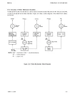
FIGURE 2-63.
Main Routine.. .................................................................
FIGURE 2-64.
Printing Routine ..............................................................
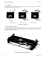
FIGURE 2-65.
Ribbon-Feed Mechanism ..................................................
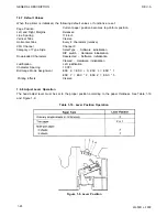
TABLE 2-1.
TABLE 2-2.
TABLE 2-3.
TABLE 2-4.
TABLE 2-5.
TABLE 2-6.
TABLE 2-7.
TABLE 2-8.
TABLE 2-9.
TABLE 2-10.
TABLE 2-11.
TABLE 2-12.
TABLE 2-13.
TABLE 2-14.
TABLE 2-15.
TABLE 2-16.
TABLE 2-17.
TABLE 2-18.
TABLE 2-19.
TABLE 2-20.
TABLE 2-21.
LIST OF TABLES
Board Connector Summary ..............................................
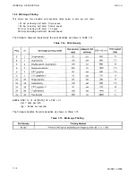
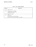
Power Supply Applications ...............................................
Control Commands.. ........................................................
Control Commands.. ........................................................
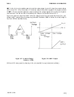
Reference Voltage ...........................................................
Current Values for Reference Voltages.. ............................ 2-39
Phase-Excitation Method.. ................................................
Drive Sequence (2-2 Excitation). .......................................
Drive Sequence (1-2 Excitation). .......................................
Chopping Current.. ..........................................................
Time Constants for Speeds.. ............................................
Acceleration Time Data (2-2 Excitation) ............................. 2-44
Deceleration Time Data (2-2 Excitation). ............................ 2-44
Acceleration Time Data (1-2 Excitation). ............................ 2-45
Deceleration Time Data (1-2 Excitation). ............................ 2-46
Excitation Sequence (Clockwise: Paper Feeds Forward). .... 2-52
Setting Time ...................................................................
E05A02LA Gate Array Functions.. .....................................
Scan Lines and DIP Switches.. .........................................
Control Commands.. ........................................................
Ribbon-Feed Gear Train ...................................................
2-iv
LQ-500/ L-1000
Summary of Contents for ActionPrinter L-1000
Page 1: ...LQ 500 L 1000 TECHNICAL MANUAL EPSON ...
Page 3: ...REV A REVISION SHEET iv LQ 500 L 1000 ...
Page 18: ...GENERAL DESCRIPTION REV A Figure 1 5 Character Matrix 1 10 LQ 500 L 1000 ...
Page 39: ...PRINCIPLES OF OPERATION REV A 2 2 LQ 500 L 1000 Figure 2 1 Cable Connections ...
Page 44: ......
Page 47: ...PRINCIPLES OF OPERATION REV A Table 2 2 Power Supply Applications 2 10 LQ 500 L 1000 ...
Page 77: ...PRINCIPLES OF OPERATION 2 40 REV A Figure 2 40 Schmitt Trigger Circuit LQ 500 L 1000 ...
Page 100: ...REV A PRINCIPLES OF OPERATION Table 2 20 Control Commands LQ 500 L 1000 2 63 ...
Page 106: ...REV A PRINCIPLES OF OPERATION Figure 2 64 Printing Routine LQ 500 L 1000 2 69 ...
Page 141: ...DISASSEMBLY ASSEMBLY AND ADJUSTMENT Table 4 5 VR2 Specifications REV A 4 26 LQ 500 L 1000 ...
Page 148: ...TROUBLESHOOTING REV A 1 Printer Does Not Operate with Power Switch ON 5 4 LQ 500 L 1000 ...
Page 149: ...REV A TROUBLESHOOTING 2 Abnormal Operation of Carriage LQ 500 L 1000 5 5 ...
Page 151: ...REV A TROUBLESHOOTING Figure 5 3 Printhead Resistance LQ 500 L 1000 5 7 ...
Page 152: ...TROUBLESHOOTING REV A 4 Abnormal Paper Feed with normal printing 5 8 LQ 500 L 1000 ...
Page 153: ...REV A TROUBLESHOOTING 5 Abnormal Operation of Control Panel LQ 500 L 1000 5 9 ...
Page 156: ...TROUBLESHOOTING REV A Table 5 6 Power Supply Circuit Unit Repair 5 12 LQ 500 L 1000 ...
Page 157: ...REV A T R O U B L E S H O O T I N G ...
Page 162: ...REV A MAINTENANCE Figure 6 2 LQ 500 L 1000 Lubrication Points LQ 500 L 1000 6 3 ...
Page 163: ......
Page 168: ......
Page 170: ...REV A APPENDIX Table A 5 µPD7810 7811 Port Functions LQ 500 L 1000 A 5 ...
Page 173: ...APPENDIX REV A Figure A 7 E01A05KA Block Diagram A 8 LQ 500 L 1000 ...
Page 174: ...REV A Table A 6 E01A05KA Pin Functions APPENDIX LQ 500 L 1000 A 9 ...
Page 185: ...APPENDIX REV A A 20 LQ 500 L 1000 ...
Page 186: ...REV A Table A 8 CN2 Connector Table A 9 CN3 Connector Cont A P P E N D I X LQ 500 L 1000 A 21 ...
Page 187: ...APPENDIX REV A Table A 10 CN4 Connector Cont Table A 12 CN6 Connector Cont A 22 LQ 500 L 1000 ...
Page 188: ...REV A APPENDIX Table A 17 Part No Reference Table LQ 500 L 1000 ...
Page 189: ...APPENDIX REV A Figure A 24 LQ 500 Exploded Diagram A 24 LQ 500 L 1000 ...
Page 190: ...REV A APPENDIX Figure A 25 M5410 Printer Mechanism Exploded Diagram LQ 500 L 1000 A 25 ...
Page 191: ...APPENDIX REV A Figure A 26 Tractor Unit A 26 LQ 500 L 1000 ...
Page 192: ......


