


REV.-A
GENERAL DESCRIPTION
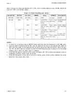
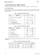
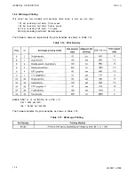
Table 1-8 shows the printer select/deselect (DC1 /DC3) control, including relations among ON-LINE, SELECT-IN
input, DC1 /DC3, and interface signals.
Table 1-8. Printer Select/Deselect Control
NOTES:
1.
In Table 1-8, it is assumed that no ERROR status exists other than that attributable to OFF-LINE mode.
2.
Once the printer is deselected by the DC3 code, the printer will not revert to the selected state unless the
DC1 code is input again. (In the deselected state, the printer ignores input data until the DC1 code is received.)
3.
The DC1 and DC3 codes are enabled only when the SLCT-IN signal (Input Connector 36 for the parallel
interface unit) is HIGH and printer power is initialized.
4.
If the SLCT-IN signal is LOW when the printer is initialized, DC1 /DC3 printer select/deselect control is
invalidated, and these control codes are ignored.
5.
If the SLCT-IN signal is HIGH and is not set to LOW by jumper 6 when printer initialized, the printer
starts from the selected (DCl) state.
LQ-500/ L-1000
1-13
Summary of Contents for ActionPrinter L-1000
Page 1: ...LQ 500 L 1000 TECHNICAL MANUAL EPSON ...
Page 3: ...REV A REVISION SHEET iv LQ 500 L 1000 ...
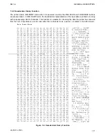
Page 18: ...GENERAL DESCRIPTION REV A Figure 1 5 Character Matrix 1 10 LQ 500 L 1000 ...
Page 39: ...PRINCIPLES OF OPERATION REV A 2 2 LQ 500 L 1000 Figure 2 1 Cable Connections ...
Page 44: ......
Page 47: ...PRINCIPLES OF OPERATION REV A Table 2 2 Power Supply Applications 2 10 LQ 500 L 1000 ...
Page 77: ...PRINCIPLES OF OPERATION 2 40 REV A Figure 2 40 Schmitt Trigger Circuit LQ 500 L 1000 ...
Page 100: ...REV A PRINCIPLES OF OPERATION Table 2 20 Control Commands LQ 500 L 1000 2 63 ...
Page 106: ...REV A PRINCIPLES OF OPERATION Figure 2 64 Printing Routine LQ 500 L 1000 2 69 ...
Page 141: ...DISASSEMBLY ASSEMBLY AND ADJUSTMENT Table 4 5 VR2 Specifications REV A 4 26 LQ 500 L 1000 ...
Page 148: ...TROUBLESHOOTING REV A 1 Printer Does Not Operate with Power Switch ON 5 4 LQ 500 L 1000 ...
Page 149: ...REV A TROUBLESHOOTING 2 Abnormal Operation of Carriage LQ 500 L 1000 5 5 ...
Page 151: ...REV A TROUBLESHOOTING Figure 5 3 Printhead Resistance LQ 500 L 1000 5 7 ...
Page 152: ...TROUBLESHOOTING REV A 4 Abnormal Paper Feed with normal printing 5 8 LQ 500 L 1000 ...
Page 153: ...REV A TROUBLESHOOTING 5 Abnormal Operation of Control Panel LQ 500 L 1000 5 9 ...
Page 156: ...TROUBLESHOOTING REV A Table 5 6 Power Supply Circuit Unit Repair 5 12 LQ 500 L 1000 ...
Page 157: ...REV A T R O U B L E S H O O T I N G ...
Page 162: ...REV A MAINTENANCE Figure 6 2 LQ 500 L 1000 Lubrication Points LQ 500 L 1000 6 3 ...
Page 163: ......
Page 168: ......
Page 170: ...REV A APPENDIX Table A 5 µPD7810 7811 Port Functions LQ 500 L 1000 A 5 ...
Page 173: ...APPENDIX REV A Figure A 7 E01A05KA Block Diagram A 8 LQ 500 L 1000 ...
Page 174: ...REV A Table A 6 E01A05KA Pin Functions APPENDIX LQ 500 L 1000 A 9 ...
Page 185: ...APPENDIX REV A A 20 LQ 500 L 1000 ...
Page 186: ...REV A Table A 8 CN2 Connector Table A 9 CN3 Connector Cont A P P E N D I X LQ 500 L 1000 A 21 ...
Page 187: ...APPENDIX REV A Table A 10 CN4 Connector Cont Table A 12 CN6 Connector Cont A 22 LQ 500 L 1000 ...
Page 188: ...REV A APPENDIX Table A 17 Part No Reference Table LQ 500 L 1000 ...
Page 189: ...APPENDIX REV A Figure A 24 LQ 500 Exploded Diagram A 24 LQ 500 L 1000 ...
Page 190: ...REV A APPENDIX Figure A 25 M5410 Printer Mechanism Exploded Diagram LQ 500 L 1000 A 25 ...
Page 191: ...APPENDIX REV A Figure A 26 Tractor Unit A 26 LQ 500 L 1000 ...
Page 192: ......


