


APPENDIX
REV.-A
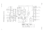
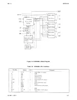
A.1.1 CPU µPD7810HG (4B)
The µPD7810/7811HG contains two 8-bit timer/counters, an 8-bit A/D converter, 256 bytes of RAM, and a
serial interface. A system can be constructed easily using this IC. The main features of this IC are as follows:
256 bytes built-in RAM (addresses FF00 hex.-FFFF hex.)
4096 bytes mask ROM (addresses 0 -0FFF hex.) for the 7811 CPU
Direct addressing of up to 64K bytes
8-bit A/D converter
158 instructions
0.8 µs instruction cycle (15 MHz)
l
16-bit event counter
Two 8-bit timer/counters
3 external and 8 internal interrupts; 6 priority levels; and 6 interrupt addresses
General-purpose serial interface (asynchronous, synchronous, and I/O modes)
I/O line (7811: 40-bit I/O port; 7810: 24-bit edge detection, 4 inputs)
Zero cross detection
l
Standby function
Built-in clock pulse circuit
l
NMOS
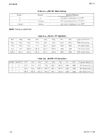
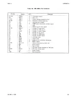
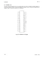
Figures A-1 and A-2 illustrate the 7810/7811 HG microprocessor, and Tables A-2 through A-5 describe its
functions.
Figure A-l. µPD7810/7811 Pin Diagram
A-2
LQ-500/ L-1000
Summary of Contents for ActionPrinter L-1000
Page 1: ...LQ 500 L 1000 TECHNICAL MANUAL EPSON ...
Page 3: ...REV A REVISION SHEET iv LQ 500 L 1000 ...
Page 18: ...GENERAL DESCRIPTION REV A Figure 1 5 Character Matrix 1 10 LQ 500 L 1000 ...
Page 39: ...PRINCIPLES OF OPERATION REV A 2 2 LQ 500 L 1000 Figure 2 1 Cable Connections ...
Page 44: ......
Page 47: ...PRINCIPLES OF OPERATION REV A Table 2 2 Power Supply Applications 2 10 LQ 500 L 1000 ...
Page 77: ...PRINCIPLES OF OPERATION 2 40 REV A Figure 2 40 Schmitt Trigger Circuit LQ 500 L 1000 ...
Page 100: ...REV A PRINCIPLES OF OPERATION Table 2 20 Control Commands LQ 500 L 1000 2 63 ...
Page 106: ...REV A PRINCIPLES OF OPERATION Figure 2 64 Printing Routine LQ 500 L 1000 2 69 ...
Page 141: ...DISASSEMBLY ASSEMBLY AND ADJUSTMENT Table 4 5 VR2 Specifications REV A 4 26 LQ 500 L 1000 ...
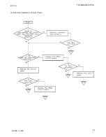
Page 148: ...TROUBLESHOOTING REV A 1 Printer Does Not Operate with Power Switch ON 5 4 LQ 500 L 1000 ...
Page 149: ...REV A TROUBLESHOOTING 2 Abnormal Operation of Carriage LQ 500 L 1000 5 5 ...
Page 151: ...REV A TROUBLESHOOTING Figure 5 3 Printhead Resistance LQ 500 L 1000 5 7 ...
Page 152: ...TROUBLESHOOTING REV A 4 Abnormal Paper Feed with normal printing 5 8 LQ 500 L 1000 ...
Page 153: ...REV A TROUBLESHOOTING 5 Abnormal Operation of Control Panel LQ 500 L 1000 5 9 ...
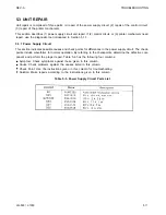
Page 156: ...TROUBLESHOOTING REV A Table 5 6 Power Supply Circuit Unit Repair 5 12 LQ 500 L 1000 ...
Page 157: ...REV A T R O U B L E S H O O T I N G ...
Page 162: ...REV A MAINTENANCE Figure 6 2 LQ 500 L 1000 Lubrication Points LQ 500 L 1000 6 3 ...
Page 163: ......
Page 168: ......
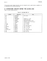
Page 170: ...REV A APPENDIX Table A 5 µPD7810 7811 Port Functions LQ 500 L 1000 A 5 ...
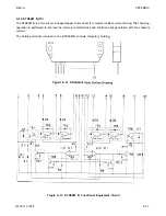
Page 173: ...APPENDIX REV A Figure A 7 E01A05KA Block Diagram A 8 LQ 500 L 1000 ...
Page 174: ...REV A Table A 6 E01A05KA Pin Functions APPENDIX LQ 500 L 1000 A 9 ...
Page 185: ...APPENDIX REV A A 20 LQ 500 L 1000 ...
Page 186: ...REV A Table A 8 CN2 Connector Table A 9 CN3 Connector Cont A P P E N D I X LQ 500 L 1000 A 21 ...
Page 187: ...APPENDIX REV A Table A 10 CN4 Connector Cont Table A 12 CN6 Connector Cont A 22 LQ 500 L 1000 ...
Page 188: ...REV A APPENDIX Table A 17 Part No Reference Table LQ 500 L 1000 ...
Page 189: ...APPENDIX REV A Figure A 24 LQ 500 Exploded Diagram A 24 LQ 500 L 1000 ...
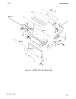
Page 190: ...REV A APPENDIX Figure A 25 M5410 Printer Mechanism Exploded Diagram LQ 500 L 1000 A 25 ...
Page 191: ...APPENDIX REV A Figure A 26 Tractor Unit A 26 LQ 500 L 1000 ...
Page 192: ......


