background image

81

and removal when there is an external weight; please use two hooks to hang on the
lifting rings during the lifting process, and gently lift it to keep it stable and not inclined;
9. The operator must read the instructions carefully before use and receive relevant
safety training to be able to handle emergencies;

2.3 Display Instrument

No.

Name

Description

1

Energy display

When all 10 cells are on, it indicates that the battery is full;

When the first cell and the second flash alternately, it

indicates that the battery is low and must be charged.

The battery remaining capacity is displayed; “100%”

indicates that the battery is fully charged.

2

Total voltage

The sum of the total voltages of the lithium battery series

3

Temperature

Battery temperature

4

Charging current

Current value when charging the lithium battery

5

Maximum cell voltage

Maximum value of cell voltage

6

Cell No. of maximum

cell voltage

The specific cell which is of the maximum voltage

7

Minimum cell voltage

Minimum value of cell voltage

8

Cell No. of minimum

cell voltage

The specific cell which is of the minimum voltage

Display status 1

Display status 2

Summary of Contents for IMOW ICE251

Page 1: ......

Page 2: ...ough our online after sales service system customers can process their warranty claims order spare parts and consult the operation manuals maintenance materials and spare parts With business all over...

Page 3: ...ference between your product and the description in this manual If you have any questions please keep in touch with the sales department or let the agents know Forklift truck ICE301B has already passe...

Page 4: ...truck started unexpected Press the emergency stop switch Set the key switch to the OFF position and remove the key 4 Before starting to operate truck Be in operating position Place directional contro...

Page 5: ...the extent that it would create a hazard 10 Truck shall be kept in a clean condition to minimize fire hazards facilitate detection of loose or detective parts Modifications and additions which affect...

Page 6: ...rsion Specifications 14 1 5 1Performance data for standard trucks 14 1 5 2Dimensions 2 Commissioning 2 1Using the Truck for the First Time 21 2 2During brake in 3 Operation 3 1Safety Regulations for t...

Page 7: ...gravity 4 6 battery maintenance 38 5 Forklift Truck Maintenance 5 1Operational safety and environmental protection 39 5 2 Maintenance Safety Regulations 39 5 3 Servicing and inspection 40 5 3 1 Maint...

Page 8: ...is considered the person who in accordance with existing contractual agreements between the owner and user of the industrial truck is charged with operational duties The proprietor must ensure that th...

Page 9: ...n The electric forklift truck is use for industrial floors and industrial elevator The capacity can be obtained from the data plate The capacity with respect to lift height and load center of gravity...

Page 10: ...nt 1 Counter weight 9 Load backrest 2 Caution light 10 Forks 3 Overhead Guard 11 Steer wheels 4 Steering wheel 12 Battery hood 5 Rearview mirror 13 Chassis 6 Mast 14 Seat 7 Headlight 15 Drive wheels 8...

Page 11: ...nit 24 Accelerator pedal 18 Lifting lever 25 Brake pedal 19 Tilting lever 26 Emergency stop switch 20 Side lever 27 Hand brake lever 21 Attachment lever 28 Steering column tilting angle 22 Caution lig...

Page 12: ...l manner that is when the wheel is turn right the truck will turn to the right When the wheel is turn left the truck will turn to the left When press the horn button it will sound 1 3 2key switch 23 T...

Page 13: ...maining charge percentage 3 LED 3 always on it indicates interlock switch opened LED 3 flashing it indicates interlock switch closed the display start timing 4 LED 4 displays the the fault code 5 LED...

Page 14: ...nload App through QR code labelled on the truck 1 Register a new account 2 Activate Bluetooth and connect the truck 3 Monitor battery status and truck location in real time 1 3 4 Emergency stop switch...

Page 15: ...ed or accelerator pedal does not have to do with the lowering speed of the forks Tilting lever button 19 The mast can be tilted by operation of this tilting lever Pulling on this lever backwards will...

Page 16: ...t back Driver sits on Pull forward the seat back adjusting switch 1 and adjust the back inclination Release the switch the seat back will be locked Safety belt Fasten safety belt before driving It pro...

Page 17: ...dard and protects the operator from falling materials It is forbidden for use a truck that does not with safeguard Fork stopper Fork stoppers are locked the forks in position To adjust fork spacing pu...

Page 18: ...l Bolt fastening label Air pressure of pneumatic tire label Notice No standing under the load carriage label Hand brake label Instruction label Gas spring indicator label Wear the helmet when driving...

Page 19: ...o not attempt to get out of the truck because the speed of overturn is much faster than you You should hold the steering wheel handle and this practice will let you in the seats It is forbidden to flu...

Page 20: ...put kw 2 Vehicle name 10 load lift height table 3 Model no 11 License no 4 Serial no 12 Load capacity kg 5 Date of build 13 Load center mm 6 Truck weight with battery kg 14 Max allowable battery weigh...

Page 21: ...t The maximum capacity is shown as a table with a given load centre of gravity D inmm and the required lift height H in mm The capacity plate of the truck indicates the truck s capacity with the forks...

Page 22: ...include battery kg 3770 2 2 Axle loading laden driving wheels steering wheels kg 5490 780 2 3 Axle loading unladen driving wheels steering wheels kg 1450 2320 3 1 Tyre type driving wheels steering whe...

Page 23: ...4 20 Length to face of forks l2 mm 2503 4 21 Overall width b1 b2 mm 1154 4 22 Fork dimensions s e l mm 40 125 1070 4 23 Fork carriage class type A B 2A 4 24 Fork carriage width b3 mm 1090 4 31 Ground...

Page 24: ...aden 15 15 5 10 Service brake type Hydraulic Mechanical park brake type Mechanical 6 1 Drive motor rating S2 60 min kW 10 6 2 Lift motor rating at S3 15 kW 12 6 3 The maximum allowed size battery mm 7...

Page 25: ...18...

Page 26: ...orks and body include tire The lift truck keeps the balance of weight between the truck body and the load on the forks with the center of the front wheels as a fulcrum when the rated capacity load is...

Page 27: ...triangle the trucks shall overturn in the corresponding direction Warning Gravity and stability The combined center that is composed of the barycenter and the load center determine the stability of li...

Page 28: ...t 2 1 1Lifting the truck by crane The Fork Lift Truck is designed for material handling only It is inappropriate for long distance transportation The Fork Lift Truck must be transported by ship train...

Page 29: ...ety measures adopted 2 1 3 Towing The towing rod on the bottom of the counter balance is used to pull and drag the truck Towing procedure You can tow the forklift to the safe place with towing rod whe...

Page 30: ...machine under light load conditions for the first stage of operation to get the most from it Especially the requirements given below should be observed while the machine is in a stage of 100 hours of...

Page 31: ...th your truck and operating procedures If there is something in the manual you do not understand ask After sales service personnel to explain it to you 2 Get permission from supervisor Only trained an...

Page 32: ...ep s and safety grip facing the truck when mounting or dismounting the truck 8 Never move controls unless properly seated Never attempt to work the controls unless properly seated Before staring adjus...

Page 33: ...ualified personnel for slinging operation should perform making use of a hook or crane arm attachment Take care not to protrude the forks out of the load The protruded fork tips may damage or turn ove...

Page 34: ...goods fallen Load bracket protect you load goods smoothly It is forbidden to use truck without safeguard or load bracket 20 Forbidden walk down or up the fork It is forbidden to walk down the fork or...

Page 35: ...ilt the mast with the load raised high 25 To handle bulky loads When handling bulky loads which restrict your vision operate the machine In reverse or have a guide When you have a guide make sure you...

Page 36: ...ea in advance 31 Back down and drive up When operating loaded truck have the rear end of your machine pointed downhill When operating unloaded truck have the rear end of your machine pointed upgrade 3...

Page 37: ...s don t operate the truck outside 35 Parking correctly Pulling the hand brake when parking on flat If necessarily parking on ramp you should place the wedges under wheels Descending and a little forwa...

Page 38: ...commissioned operated or a load unit lifted the driver must ensure that there is nobody within the hazardous area Checks and operations to be performed before starting daily work Visually inspect the...

Page 39: ...t earlier than as with the front wheel steering car Stopping or parking the truck Slow down and press the brake pedal to stop the truck Place the travel combination switch in neutral Down the forks on...

Page 40: ...e deposit area slow down your truck Once stop the truck right in front of the area where your load is to be deposited Check the condition of the deposit position Tilt the mast forward until forks beco...

Page 41: ...o 20 cm above the ground Tilt the mast backward fully and move to the desired area 3 2 5Check after operation Clean and check the truck after operation Damage or leakage Add grease if necessarily Chec...

Page 42: ...e connection Not allowing changing from anode to cathode otherwise resulting in sparkle burning and explosion 4 Do not overuse battery If you use up the energy of battery till the forklift immovabilit...

Page 43: ...battery connector are not close or which destroys connector and electrical units as a rule 4 3 1 Charging Procedure Insert the electric switch key and turn clockwise Tilt the lift mast forwards slight...

Page 44: ...y 1 Press the switch 1 open the battery hood 2 expose the battery 2 Disconnect the battery wires harness from the truck 3 Attach the lifting hook to the battery 4 Sling the battery to a certain height...

Page 45: ...38 4 5Battery maintenance 1 Remaining clean battery Keep dryness and cleanness on the surface of battery the point for connecting with wire is also dry and clean See the APPENDIX...

Page 46: ...l service centre Lifting and jacking up When the Forklift Truck is to be lifted the lifting gear must only be secured to the points specially provided for this purpose When jacking up the Forklift Tru...

Page 47: ...ance of the Forklift Truck When replacing factory fitted tyres only used original manufacturer s spare parts as otherwise the data plate specifications will not be kept When changing wheels and tyres...

Page 48: ...and relays Fix the motor and cable Power supply Visually inspect battery Visually inspect battery plug Check battery cable connections are secure grease terminals if necessary Travel Check transmissi...

Page 49: ...Load handler and Pallet for wear and damage Perform sight check of rollers sliding elements and stops Steering system Test electric steering Check steering toothing for wear and lubricate Lubrication...

Page 50: ...43 5 4 Lubrication Schedule...

Page 51: ...44...

Page 52: ...bles of different grades The only exception to this is when mixing is expressly stipulated in the Operating Instructions Avoid spillage Spilled liquids must be removed immediately with suitable bondin...

Page 53: ...ICE301B 2500 38 2500 34 2700 38 2700 34 3000 42 3000 36 3300 42 3300 36 3600 40 3500 38 4000 42 3600 38 3 stage Mast ICE301B 4300 38 4000 42 4500 40 4300 42 4800 42 4500 44 5000 44 5500 46 6000 48 Mas...

Page 54: ...nt accidental roll Make sure the travel combination switch on neutral position 2 Pull up the hand brake lever 3 Shut off switch and control the lift and tilt lever several times so that the inner pres...

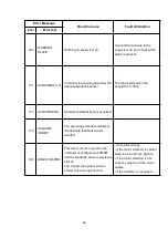
Page 55: ...ted capacity see 1 5 1Performance data for standard trucks Trouble Probably cause Method of troubleshooting Too much noise When traveling or change direction Gear clearance is too big Too much worn of...

Page 56: ...iding valve or blocking in valve Adjust pressure or clear dirt 5 Too high viscosity oil Replace wrong oil 6 The steering fails to return to its natural position due to breakage of locking spring or in...

Page 57: ...ontrol valve then goes to lifting cylinder or tilting cylinder When lifting and tilting spool is in neutral the lifting pump is out off work When pulling lifting spool high pressure oil goes to the bo...

Page 58: ...d from loose suction side joint Retighten each joint Cavitation due to too high oil viscosity replace with new oil having proper viscosity for temperature at which pump is to be operate to operate whe...

Page 59: ...lve assembly Lowering distance of mast is big when spool valve is in the center Valve body and spool valve is worn and clearance between them is too great Replace spool valve with specified clearance...

Page 60: ...f 300mm the main relieve valve is all right Otherwise adjust it as step 3 3 If the forklift can t work enhance the pressure main relieve valve remove the front soleplate loosen the tightening nut of t...

Page 61: ...Carriage bracket assembly out of adjustment Adjust clearance with thrust metal and carriage side roller 2 Insufficient clearance between inner and outer masts or rollers and mast Adjust clearance wit...

Page 62: ...ting in excessive inner leaks Replace Yx ring 3 Springs of the multiple control valve and its relief valve are inoperative oil leaks Replace 4 Excessive wear occurs of the hydraulic control valve resu...

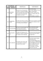
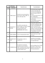
Page 63: ...t solved replace the logic board 176 HOME SENS ERR XX The controller detected a difference between the estimated absolute orientation of the rotor and the position of the index signal ABI encoder It i...

Page 64: ...the hardware Each controller produced is signed at the end of line test with a specific code mark saved in EEPROM according to the customized Part Number According with this sign only the customized...

Page 65: ...AILURE 3 A hardware problem in the logic board due to high currents overload An overcurrent condition is triggered even if the power bridge is not driven The failure lies in the controller hardware Re...

Page 66: ...mpedance between U V and W terminals and Batt terminal of the controller Check the motor leakage to truck frame If the motor connections are OK and there are no external low impedance paths the proble...

Page 67: ...FETs and expects the phase voltages increase toward the positive rail value If one phase voltage is below 66 of the rail voltage this alarm occurs Cause2 If the problem occurs at start up the LC does...

Page 68: ...checks if the contactor is stuck The controller drives the power bridge for several dozens of milliseconds trying to discharge the capacitors bank If the capacitor voltage does not decrease by more th...

Page 69: ...s 196 MOT PHASE SH 36 MOT PHASE SH 37 MOT PHASE SH 38 Short circuit between two motor phases The number that follows the alarm identifies where the short circuit is located 36 U V short circuit 37 U W...

Page 70: ...ts are activated at the same time Check if there are wrong connections in the external wiring Using the TESTER function verify that inputs are in accordance with the actual state of the external switc...

Page 71: ...assistance to your dealer technician in order to verify that the maximum current that can be supplied by the hardware is not exceeded In case no failures problems have been found the problem is 202 VD...

Page 72: ...ck from the encoder has a jump higher than 40 Hz in few tens of milliseconds This condition is related to an encoder failure Check the electrical and the mechanical functionality of the encoder and th...

Page 73: ...ER ABI PWM The controller does not detect correct information on PWM input at start up Re cycle the key Check the sensor in order to verify that it works properly Check the wiring If the problem occur...

Page 74: ...arge and the BATTERY CHECK setting is other than 0 refer to SET OPTION menu Check the battery charge and charge it if necessary If the battery is actually charged measure the battery voltage through a...

Page 75: ...ND Absolute feedback sensor acquired 172 ACQUIRE ABORT The acquiring procedure relative to the absolute feedback sensor aborted 168 SIN COS D ERR This alarm occurs only when the controller is configur...

Page 76: ...rnal components Replace the logic board 214 EVP COIL OPEN No load is connected between the NEVP output A19 and the electrovalve positive terminal Check the EVP condition Check the EVP wiring If the pr...

Page 77: ...ppears at key on without any CLEAR EEPROM performed replace the controller 241 COIL SHOR EVAUX This alarm occurs when there is an overload of one or more EV driver As soon as the overload condition ha...

Page 78: ...nce with the parameters set If the problem is not solved replace the controller 246 EB DRIV OPEN The EB coil driver is not able to drive the load The device itself or its driving circuit is damaged Th...

Page 79: ...he wirings Check if there are failures in the micro switches 228 TILLER OPEN Tiller seat input has been inactive for more than 30 seconds Activate the tiller seat input Check the tiller seat input sta...

Page 80: ...read by the microcontroller is at its maximum value without the hand brake request Check the mechanical calibration and the functionality of the brake potentiometer If the alarm is still present repla...

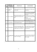
Page 81: ...ontacts being open Verify the EPS functionality 78 VACC NOT OK At key on and immediately after that the travel demands have been turned off This alarm occurs if the ACCELERATOR reading in TESTER funct...

Page 82: ...CC function Acquire the maximum and minimum potentiometer values through the PROGRAM VACC function If the alarm is still present check the mechanical calibration and the functionality of the accelerat...

Page 83: ...The voltage read by the microcontroller at the steering sensor input is not within the STEER RIGHT VOLT STEER Acquire the maximum and minimum values coming from the steering potentiometer through the...

Page 84: ...77 APPENDIX...
Page 85: ...nstructions 2 2 1 Battery Introduction 2 2 2 Instructions 2 2 3 Display Instrument 3 2 4 Battery Nameplate 4 Chapter 3 Charging 5 Chapter 4 Storage 7 Chapter 5 Transportation 7 Chapter 6 Common Proble...

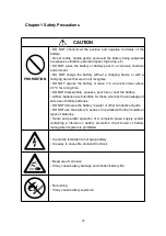
Page 86: ...or a long time DO NOT disassemble squeeze puncture or heat the battery Lithium batteries are forbidden for those who lack the knowledge of safe use of lithium batteries DO NOT immerse the battery in w...

Page 87: ...e charged in time to avoid damage caused by over discharge of the battery after self discharge 4 Do not place metal objects such as wrenches knives on the lithium battery or other objects that may cau...

Page 88: ...e second flash alternately it indicates that the battery is low and must be charged The battery remaining capacity is displayed 100 indicates that the battery is fully charged 2 Total voltage The sum...

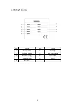
Page 89: ...82 2 4 Battery Nameplate No Name No Name 1 Battery model 4 Cell Type 2 Nominal Voltage 5 Nominal Capacity 3 Nominal Energy 6 Version NO 7 Battery Weight 8 Date 9 Serial No...

Page 90: ...r overcharge 5 When charging connect the battery plug connector to the charger plug connector and there will be contactor sound after starting charging the circular display meter will display the tota...

Page 91: ...be stored in a temperature environment of 0 C 40 C 3 Store in a dry ventilated and cool environment avoid direct sunlight high temperature high humidity corrosive gas severe vibration etc 4 DO NOT sta...

Page 92: ...hould be avoided and throwing rolling inverting squeezing and excessive stacking are prohibited 2 Prevent rain during transportation 3 Ensure that the battery or battery pack has been disconnected fro...

Page 93: ...s looseness cracks cracks in the insulation layer burn marks etc of the battery s pole pressing bolts conductive strips main circuit wires and connectors are found before and during the installation s...

Page 94: ...exposed to heavy rain during use 5 Estimate the charging time and discharging time of the battery according to the actual status of use of the battery or battery pack observe whether there is any abn...

Page 95: ...e that the resistance value meets the Chinese national standard 500 V and to ensure that there is no electric leakage with the battery once a month 7 3 Disposal of Used Battery Packs To prevent enviro...

Reviews: