48
REV. 09/2016
OPERATING SYSTEM
6
Testing
-
-
Check if the push button switch circuit is
connected;
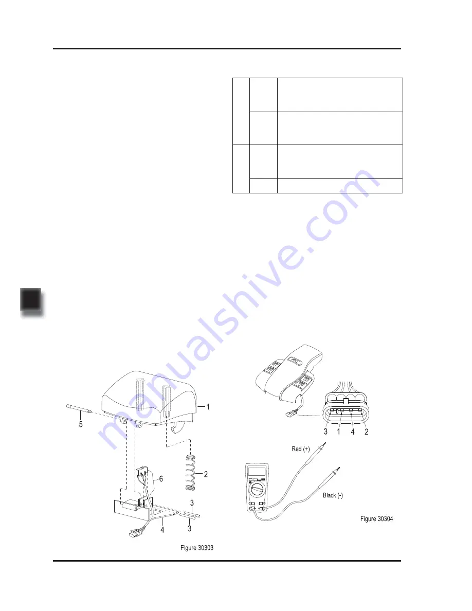
Carry out ON/OFF test to the push button
switch with a multimeter:
Emergency Reverse
Switch
Lifting/Lowering Button
(See Figure 30302)
-
-
-
Remove switch assembly (5 or 9) form cap
(1);
Remove pin (6) securing buttons and remove
the lifting button (2 or 7) , the lowering button
(3 or 8) and springs (4).
Install according to the reverse order of rem-
oval.
Horn Button
(See Figure 30302)
-
-
Unscrew three screws (11) and remove bra-
cket (20) and springs (19) and horn button
(17).
Install according to the reverse order of rem-
oval.
Emergency Reverse Switch
(See Figure 30303)
-
-
-
Remove pin (5) securing button and remove
the emergency reverse button (1) and springs
(2) from bracket (4).
Remove pin (3) and remove the emergency
reverse switch (6).
Install according to the reverse order of rem-
oval.
Emergency Reverse
Button
6.2.2 Faults and Causes
1
Fault
Operate the push button switch,
but the vehicle responds with no
action
Cause
a. Push button switch failure;
b. Push button switch circuit not
conducted.
2
Fault
Push button switch not operated,
but the vehicle responds with
action
Cause Pushbutton switch failure
Checking
-
Check if the pushbutton switch and the
appearance of cables are in good condition,
and if the plug connection is secure.
6.2.3 Checking and Testing
Summary of Contents for EPT20-15ET
Page 1: ...Service Manual Electric Pallet Truck EPT20 15ETL EPT20 15ET ...
Page 2: ...Service Manual Electric Pallet Truck EPT20 15ETL EPT20 15ET ...
Page 10: ...REV 09 2016 TABLE OF CONTENTS ...
Page 12: ...1 1 1 INFORMATION SPECIFICATIONS ...
Page 13: ...2 NOTE ...
Page 19: ...REV 09 2016 INFORMATION SPECIFICATIONS 1 8 ...
Page 20: ...9 2 2 MAINTENANCE ...
Page 21: ...10 NOTE ...
Page 29: ...18 REV 09 2016 MAINTENANCE 2 ...
Page 30: ...19 3 3 STRUCTURE FUNCTIONS ...
Page 31: ...20 NOTE ...
Page 37: ...26 REV 09 2016 STRUCTURE FUNCTIONS 3 ...
Page 38: ...27 4 4 CHASSIS SYSTEM ...
Page 39: ...28 NOTE ...
Page 44: ...33 5 5 DRIVE SYSTEM ...
Page 45: ...34 NOTE ...
Page 55: ...44 REV 09 2016 DRIVE SYSTEM 5 ...
Page 56: ...45 6 6 OPERATING SYSTEM ...
Page 57: ...46 NOTE ...
Page 64: ...53 7 7 HYDRAULIC SYSTEM ...
Page 65: ...54 NOTE ...
Page 67: ...56 REV 09 2016 HYDRAULIC SYSTEM 7 7 1 1 Hydraulic Schematic Diagram ...
Page 81: ...70 REV 09 2016 HYDRAULIC SYSTEM 7 ...
Page 82: ...71 8 8 ELECTRICAL SYSTEM ...
Page 83: ...72 NOTE ...
Page 107: ...REV 09 2016 ELECTRICAL SYSYTEM 8 96 ...
Page 108: ...97 9 9 TROUBLESHOOTING ...
Page 109: ...98 NOTE ...
Page 114: ...103 APPENDIX ...
Page 115: ...104 NOTE ...
Page 116: ...105 B B SERVICE MANUAL BATTERY ...
Page 117: ...106 NOTE ...
Page 126: ...115 C C SCHEDULE ...
Page 127: ...116 NOTE ...


