background image

17

EN

Important notice

Unprofessional installation may cause 

a fire hazard! Please read these installation 
instructions carefully. In particular, please 
observe the dimensions stated and the fol-
lowing notes.

• 

This device can be used by children aged 
8 upwards and by persons with physical, 
sensory, or mental disabilities, or who 
have inadequate experience and know-
ledge if they are supervised or if they have 
received adequate instruction in how to 
use the device safely and understand the 
associated risks. 

• 

Children must be supervised to ensure 
they do not play with the unit. 

• 

Children and persons who have not re-
ceived proper instruction must not clean 
or service the system.

•  The infrared radiator is intended for a 

connection voltage of 230 V 50 Hz via an 
infrared controller.

•  Installation and connection to the infrared 

controller must be carried out in accord-
ance with the connection diagram.

•  Before the infrared radiator is operated via 

the controller, check that all connectors 
are firmly connected with no risk of com-
ing loose.

• The EU 60335-2-53 (VDE  0700 Part 53) 

regulations are to be complied with inside 
the infrared cabin.

•  Only the number of infrared radiator spec-

ified for the size of the booth should be as-
sembled in the infrared cabin. Please ask 
your cabin manufacturer or dealer.

• One of the controllers specified below 

should be used to regulate or control the 
infrared emitter.  This controller should be 
mounted in the infrared cabin in accord-
ance with the installation instructions.

• 

 Attention: Covering the infrared ra-

diator causes a fire risk!

• The installation of the infrared radiator 

in the cabin must be carried out in such a 
way to assure even all-round emission for 
the user.

•  The infrared radiator is not suitable to in-

stallation on the cabin ceiling.

•  If the infrared radiator is installed in the 

back zone, then appropriate protective 
measures must be taken to ensure that the 
flocked protection grille cannot be pressed 
in unintentionally (e.g. a wooden grille 
mounted in front).

•  Take care to ensure that the main energy 

discharge occurs through the infrared ra-
diation.

  Additionally, however, a thermal heat dis-

charge arises at the housing in the vertical 
installation.  This heat can overheat the 
surrounding wood!  Caution: fire risk!

Summary of Contents for VITAE

Page 1: ...INNOVATIVE SAUNA TECH NOLOGY Made in Germany Vitae protect Druck Nr 29344822 05 20 D Montage und Gebrauchsanweisung Assembly and operating instruction EN RU Infrarotw rmestrahler Infrared radiator...

Page 2: ...2 Deutsch 3 English 15 27...

Page 3: ...r optional 7 Elektrischer Anschluss 8 Planungshinweise 9 Mindestabst nde 9 Montage 10 12 Einbaubeispiel 10 Senkrechte Montage an der Kabinenwand 10 Senkrechte Montage in den Kabinenecken 10 Stecker mo...

Page 4: ...die Funktion beeintr chtigen und ist nicht zul ssig Jegliche nicht autorisierte technische Ver nderung f hrt zum Verlust der Ge w hrleistung Sehr geehrte Kundin sehr geehrter Kunde Sie haben ein hochw...

Page 5: ...f r die Kabinengr e angegeben Bitte fragen Sie Ihren Kabinenhersteller oder H ndler Allgemeine Sicherheitsbestimmungen F r die Regelung bzw Steuerung der In frarotstrahler ist ein geeignetes Steuerge...

Page 6: ...vorhan den auf der Kabinendecke angebracht sein BeachtenSie dassderEmitterimInfrarot W rmestrahler keinen mechanischen Be lastungen St e Druck ausgesetzt wird IstderEmittereinmalgebrochen wasaber bei...

Page 7: ...sche Daten Spannung 230 V 1N 50 Hz Gewicht ca 2 5 kg Leistung Vitae protect 350 W mit und ohne Schutzgitter Vitae protect 500 W mit und ohne Schutzgitter Vitae protect 750 W mit und ohne Schutzgitter...

Page 8: ...e ist der Stecker nicht vormon tiert Montieren Sie den Stecker nachdem Sie die Leitung verlegt haben siehe Montage Falls Ihr Steuerger t mit der entsprechenden Leitung mit Anschlussbuchse ausgestattet...

Page 9: ...betragen Der Mindestabstand von Strahlerunterkante zum Holzfu boden der Kabine muss bei ver tikaler Montage 50 cm und bei horizontaler Montage 9 cm betragen Siehe Abb 4 Der waagerechte MIndestabstand...

Page 10: ...ie Verbindungsleitung durch die Wand nach oben Achten sie darauf dass die Strahlerseite mit Kabelanschluss nach unten zeigen muss F hren Sie den Strahler in die vorbereitete ff nung ein Mit den beigef...

Page 11: ...er braun Montage schrauben 1 Kontakte in das Mittelteil fest einstecken bis sie einrasten Auf die korrekte Ausrichtung des Mittelteils achten N PE L blau braun gelb gr n Abb 9 Abb 10 Richtige Ausricht...

Page 12: ...frei austreten k nnen Brandgefahr Inspizieren Sie die Kabine vor jeder Inbetriebnahme AchtenSieinsbesondere darauf das keine Gegenst nde auf bzw direkt vor dem IR Emitter abgelegt wer den Brandgefahr...

Page 13: ...ycling Bitte diese Adresse zusammen mit der Montageanwei sung gut aufbewahren Damit wir Ihre Fragen schnell und kompetent beantwor ten k nnen geben Sie uns immer die auf dem Typen schild vermerkten Da...

Page 14: ...kte sind f r den St ckgut versand Palette konzipiert Wir weisen an dieser Stelle ausdr cklich darauf hin dass unsereVerpackungen nicht f r den Einzelversand per Paketdienst geeignet sind F r Sch den d...

Page 15: ...ccessories optional 19 Electrical connection 20 Planning advice 21 Minimum distances 21 Assembly 22 24 Assembly example 22 Flush mounted installation 22 Vertical installation in corners 22 Connection...

Page 16: ...the delivering transport company or please consult the supplier who provided the equipment to you Caution Risk of fire by incorrect in stallation Make sure to read the installati on manual Pay particu...

Page 17: ...om ing loose The EU 60335 2 53 VDE 0700 Part 53 regulations are to be complied with inside the infrared cabin Only the number of infrared radiator spec ifiedforthesizeoftheboothshouldbeas sembled in t...

Page 18: ...gram An optional plug adaptor may be used to facilitate the connection Upto5infraredradiatormaybeconnected to the control unit through one line using such plug adaptor For practical reasons the connec...

Page 19: ...Voltage 230 V 1N 50 Hz Weight ca 2 5 kg Power Vitae protect 350 W with and without grid Vitae protect 500 W with and without grid Vitae protect 750 W with and without grid Dimensions HWD 950 x 200 x 6...

Page 20: ...semble the plug after you have installed the cable If your control unit has the corresponding ca ble with plug connect the IR radiator using this plug Otherwise you can alternatively use the special c...

Page 21: ...ibutes to a more pleasurable heat experience The intensity of Vitae emitters can be quick ly adjusted using an optionally available wall mounting IR dimmer item 4954 which can be mounted inside IR cab...

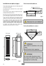
Page 22: ...ds unless others is specified by the cabin manufacturer For details and safety gaps please refer to the illustrations shown in Fig 4 5 6 and 7 Installation example and gaps Flush mounted installation...

Page 23: ...t the three contacts into the three corre sponding holes of the middle part firmly until they snap in Pay attention to the correct posi tion of the L N and Gr wires N Gr L blue brown yellow green Fig...

Page 24: ...use In particular ensure that no objects are placed on or directly in front of the IR ra diator Risk of fire CAUTION Makesuretoobservethesafetygapsgiv eninFig 5byinstallationofthefootzone IR radiator...

Page 25: ...your questions quickly and compe tently please provide the information printed on the type shield including the model item no and serial no in all inquiries Equipment commissioning date ______________...

Page 26: ...roducts is designed for the ship ping of individually packed goods pallet We expressly point out that our packaging is not suitable for individual shipments via parcel post The manufacturer shall acce...

Page 27: ...27 RU 28 30 31 32 32 35 33 33 34 35 36 36 37 38 ASB 38...

Page 28: ...28 RU...

Page 29: ...29 RU 8 230V50Hz EU 60335 2 53 VDE 0700 53...

Page 30: ...30 RU 3 5...

Page 31: ...1 3 3 x 1 5 2 2 3 230 50 2 5 protect 350 protect 500 protect 750 950 x 200 x 60 1 4 nm 10 nm IR A 0 78 1 4 m 20 IR B 1 4 3 0 m 60 IR C 3 0 m 20 94 6596 94 2046 94 4960 2 5 94 4396 1 2 94 2046 94 4960...

Page 32: ...32 RU 1 3 5 2 4 7 9 6 8 5 9 94 4396 94 2046 2 2b 3 5 1 3500 750 4 9 3 5 3b 2 2b 2 5 944396 944960 942046 3500...

Page 33: ...33 RU 3 3 750 50 350 500 15 4 94 4954 9 min 50 cm min 7 cm IR Emitter Vitae min 15 cm min 9 cm 7 50 9 4 4 6...

Page 34: ...34 RU 6 7 5 6 7 4 5 6 7 5 950 200 940 178 167 693 60 Holzschutz 40 mm 164 mm 178 mm 17 mm 60 mm 90 164 mm 178 mm 17 mm 60 mm...

Page 35: ...35 RU 8 3 8 N PE L 1 N PE L 9 10 2 11 3 2 12 11...

Page 36: ...36 RU 5 4...

Page 37: ...37 RU EOS Saunatechnik GmbH Schneiderstriesch 1 35759 Driedorf Germany EOC 108811 928 7 495 66 55 192 8 800 1000 539 info eos sauna ru www eos sauna ru...

Page 38: ...38 RU ASB I II III IV V VI 24 06 2015...

Reviews: