background image

5

EN

“splash protected” version in accordance 
with DIN EN VDE 0100 T 703. Therefore, 
only VDE-tested sauna light with max. 40 
Watt may be installed in connection with 
the sauna heater. 

• 

 Only a locally certified electrician 

may connect the sauna facility (sauna 
heater, control unit, lighting etc.) to a fixed 
mains connection.

• 

All electrical installations and all connec-
tion lines that are installed inside the cab-
in must be suitable for an ambient tem-
perature of at least 170 °C. If single-wire 
cables are used as connection lines, they 
must be protected using a flexible metal 
tube connected to the equipment ground-
ing conductor. Please see the table for the 
minimum cross-section of the connection 
cable and the suitable cabin size in rela-
tion to the power input in kW.

• 

When installing the sauna heater, please 
ensure that the vertical clearance be-
tween the sauna heater upper edge and 
the sauna ceiling is maintained. Please 
see also the dimensions diagram for the 
clearance between the lower edge of the 
sauna heater and the floor. On heaters 
with bases, this clearance is maintained 
via the base or legs of the device. 

• 

Floor heating in the sauna cabin increases 
the surface temperature of the flooring.

• 

Please see the dimensions information 

for the respective sauna heater for the 
clearance between the heater protective 
grating or the bench and other flammable 
materials. The heater protective grating 
must roughly accord with the front height 
of the sauna heater.

• 

Please also observe the information and 
instructions provided by the cabin manu-
facturer.

• 

 Please take precautions when 

cleaning components with sharp edges.

• 

Upright heaters need to be fitted on site 
with elements that prevent them from 
overturning.

• 

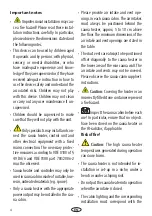
 Attention:

 Pour the infusion water 

only on the sauna rocks and never any-
where else.

• 

When using your sauna in a dry 

Finnish mode never add sauna essences or 
place any herbs into the vaporizer holder 
for essences/herbs. 

Fire hazard!

• 

 Never add more essences or vol-

atile oils than advised on the packaging. 
Never use alcohol or undiluted concen-
trates.Caution! 

Fire hazard!

• 


When designing the cabin ensure 

that the external exposed glass surfaces 
only reach a maximum temperature of 
76°C. If necessary, protective features 
need to be fitted.

Summary of Contents for Filius Control

Page 1: ...INNOVATIVE SAUNA TECHNOLOGY MADE IN GERMANY Druck Nr 29345062 en 18 19 Filius Control 400 V 3N AC 230 V 1N AC EN Installlation and operating instruction...

Page 2: ...ications 6 Connection example 400 V 3N 8 Connection example 230 V 1N 9 Installation of the Filius Control 10 Minimum distances 10 Commissioning 12 Position change control panel left right 13 Replaceme...

Page 3: ...pped the goods Please note that you will only be able to achieve anoptimumsaunaclimateifthecabinwithitsair intake and ventilation the sauna heater and the control unit are aligned to each other Please...

Page 4: ...eofsuitable low resin untreatedmaterials e g spruce Only a sauna heater with the appropriate power output may be installed in the sau na cabin Please provide air intake and vent ope nings in each saun...

Page 5: ...floor On heaters with bases this clearance is maintained via the base or legs of the device Floor heating in the sauna cabin increases the surface temperature of the flooring Please see the dimension...

Page 6: ...able exits the sauna heater and guide this cable outside through the hole to the control unit The cable and all other connecting cables mains power cables and cabin lighting should be installed in ins...

Page 7: ...AC Anschluss an 230V 1NWechselstrom m glich Power rating 4 5 kW 6 0 kW 7 5 kW For sauna size 4 6 m 6 8 m 7 10 m Min size air inlet and exhaust vent 35 x 11 cm Weight without stones and packing 15 kg...

Page 8: ...ite Connection example for 400V 3N AC 4 5 kW 3x 1500 W 6 0 kW 3x 2000 W 7 5 kW 3x 2500 W Power acc DIN Electrical connection Fuse protection Connecting cable main heater 4 5 kW 400V 3N AC 50 Hz 3 x 16...

Page 9: ...re given for 230V 1N power supply Specifications for 230V 1N connection 4 5 kW 3x 1500 W 6 0 kW 3x 2000 W 7 5 kW 3x 2500 W A1 A2 A3 B1 B2 B3 Thermostat Sicherheits temperaturbegrenzer M Zeitschaltuhr...

Page 10: ...all so that there is approx 3 mm space between the wall and the head of the screw Fig 2 2 berpr fen Sie dass die Zuleitung span nungslos ist um die Ofenzuleitung an zuschlie en First unscrew the four...

Page 11: ...and the two lock screws U V W N N PE N Z Y X L N PE 230V AC A Strahlblech U V W N N PE N Z Y X 400V 3N AC Fig 4 1 Connection line Screws 4 2 x 9 5 Corrugated head screws 2 9 x 19 Connection terminal...

Page 12: ...necessary The design of the cabin can impact on the way the cabin heats up and cause tem perature differences of up to 15 C Also many bimetal thermometers wall moun ted react sluggishly so that the re...

Page 13: ...13 EN Position change control panel left right safety screw 2 9 x 19 Fig 1 Fig 2 Fig 3 Fig 5 Fig 4 2 1 6 180 4 7 8 9 3 10 5...

Page 14: ...14 EN Replacement of heating elements Fig 1 Fig 2 Fig 4 Fig 3 1 3 2 6 7 4 5...

Page 15: ...more essences or volatile oils than advised on the packaging Never use alcohol or undiluted concentrates Cau tion Fire hazard All sauna heating units are made of low corro sion material To enjoy your...

Page 16: ...l units will be protected by this ELCB Under current manufacturing technology it is not reasonable to use heating elements for sau na heaters which do not collect moisture from the surrounding air It...

Page 17: ...your questions quickly and compe tently please provide the information printed on the type shield including the model item no and serial no in all inquiries Equipment commissioning date ______________...

Page 18: ...roducts is designed for the ship ping of individually packed goods pallet We expressly point out that our packaging is not suitable for individual shipments via parcel post The manufacturer shall acce...

Reviews: