36
GB
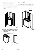
Sensor installation
In contrast to the information on sensor instal-
lation in the installation instructions for your
sauna control unit, the sensor for this heater
is mounted centrally above the heater on the
cabin wall, 5 cm below the ceiling (Fig. 6).
Sensor
5
cm
Fig. 8
Fig. 7
9. After that put the cover panel back on and
secure it with 4 screws.
A
Ansicht
A
Screws 4,2 x 9,5
Securing
screws
8. Screw the supplied refl ector shield as shown
in pic. 5 with 3 screws 4.2 x 9.5 and the 2 Se-
curing screws.
Fig. 6
Corrugated-
head screws
6. Hook the sauna heater with the rear wall re-
ceiving slots onto the fi xing screws.
7. Secure the heater on the sauna wall behind it
using 2 screws through the holes in the rear
upper edge of the heater (see fi g. 6) or alter-
natively secure it to the side wall, as shown
on fi g. 7.
Summary of Contents for Bi-O Filius
Page 2: ...2 Deutsch 3 English 20 o 37...
Page 16: ...16 D Auswechseln von Rohrheizk rpern 1 3 2 Abb 1 Abb 2 Abb 3 Abb 4 Abb 5...
Page 37: ...37 D Replacment of heating elements 1 3 2 Fig 1 Fig 2 Fig 3 Fig 4 Fig 5...
Page 45: ...34 RU DIN EN ISO 9001 2000 110 C 30 40 C 110 C 20 25 85 C 80 90 C...
Page 46: ...35 RU 8 VDE 0100 49 DA 6 VDE 0100 703 2006 2 5 10...
Page 47: ...36 RU DIN EN VDE 0100 T 703 40 170 C...
Page 48: ...37 RU S Guard...
Page 52: ...52 RU 4 3 4 4 2 5 2 2 3 3 3 3a 6 2 5 6 5 6 A Ansicht A 4 2 x 9 5 8 7 3 4 2 9 5...
Page 53: ...53 RU 5 7 5 cm 7...
Page 55: ...55 RU 4 3 4 4 2 5 5 2 2 3 3 3 3a 5...
Page 56: ...56 RU A Ansicht A 5 6 5 cm 8 6 7 4 2 x 9 5 9 8 3 4 2 9 5 6 7 2 6 7...
Page 57: ...57 RU 1 3 2 1 2 3 4 5...
Page 58: ...58 RU 2 1 3 4 5 6 180 1 2 3 4 5 7 8 9 10 3 mm 2 1 6 28 3 mm 6 7...
Page 59: ...54 RU 4 5 5 1 0 8 4 II Ill 10...
Page 60: ...44 RU 100 10...
Page 62: ...46 RU RMA RMA RMA 3 1 2 2 RMA...

