35
GB
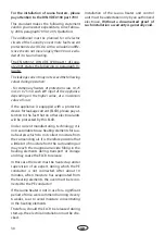
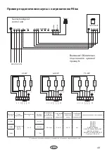
3. Make the cable connections according to the
wiring diagram. The corresponding wiring
diagram is given in this manual (fi g. 4).
power supply cable
Fig. 4
4. Install the terminal block back into the origi-
nal position in the heater and fasten it with
two screws.
5. The terminals for connection of the vaporizer
are placed on the left side of the heater. Make
the cable connections to the vaporizer as de-
scribed above (see fi g. 5).
2. In order to connect the power supply cable
fi rst undo both screws as shown in fi g. 3 and
pull the terminal block downwards (fi g. 3a).
Fig. 3
Fig. 3a
Fig. 5
Connection terminal
power supply cable
Cable screw connection
Cable screw connection
Connection terminal
Summary of Contents for Bi-O Filius
Page 2: ...2 Deutsch 3 English 20 o 37...
Page 16: ...16 D Auswechseln von Rohrheizk rpern 1 3 2 Abb 1 Abb 2 Abb 3 Abb 4 Abb 5...
Page 37: ...37 D Replacment of heating elements 1 3 2 Fig 1 Fig 2 Fig 3 Fig 4 Fig 5...
Page 45: ...34 RU DIN EN ISO 9001 2000 110 C 30 40 C 110 C 20 25 85 C 80 90 C...
Page 46: ...35 RU 8 VDE 0100 49 DA 6 VDE 0100 703 2006 2 5 10...
Page 47: ...36 RU DIN EN VDE 0100 T 703 40 170 C...
Page 48: ...37 RU S Guard...
Page 52: ...52 RU 4 3 4 4 2 5 2 2 3 3 3 3a 6 2 5 6 5 6 A Ansicht A 4 2 x 9 5 8 7 3 4 2 9 5...
Page 53: ...53 RU 5 7 5 cm 7...
Page 55: ...55 RU 4 3 4 4 2 5 5 2 2 3 3 3 3a 5...
Page 56: ...56 RU A Ansicht A 5 6 5 cm 8 6 7 4 2 x 9 5 9 8 3 4 2 9 5 6 7 2 6 7...
Page 57: ...57 RU 1 3 2 1 2 3 4 5...
Page 58: ...58 RU 2 1 3 4 5 6 180 1 2 3 4 5 7 8 9 10 3 mm 2 1 6 28 3 mm 6 7...
Page 59: ...54 RU 4 5 5 1 0 8 4 II Ill 10...
Page 60: ...44 RU 100 10...
Page 62: ...46 RU RMA RMA RMA 3 1 2 2 RMA...

