background image

30

SHADING

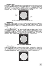
FIGURE 4-1.  SHADING

NOTE:

Verify that any shading is not the result of improper eye-relief adjustment.

B. Edge Glow 

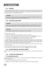
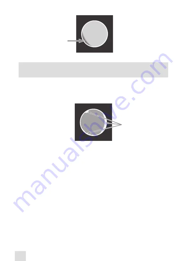
Edge glow is a bright area (it sometimes appears to be sparkling) in the outer portion of the viewing 

area (see Figure 4-2). To check for edge glow, block out all light from the device by cupping a hand over 

the lens. If the image tube is displaying edge glow, the bright area will still show up; if edge glow occurs, 

please contact Customer Support. 

EDGE
GLOW

FIGURE 4-2.  EDGE GLOW

C. Flashing, Flickering, or Intermittent Operation

The image may appear to flicker or flash. If there is more than a single flicker, check for a loose battery 

adapter or a weak battery. If flickering continues, please contact Customer Support. 

4.3.2    COSMETIC BLEMISHES

Cosmetic blemishes are usually the result of manufacturing imperfections. They 

do not 

affect the reli-

ability of the image intensifier, and are not normally a cause for returning the NYX-14.  However, some 

types of cosmetic blemishes can worsen over time and interfere with the user’s ability to properly oper

-

ate the device during missions. If you believe a cosmetic blemish is cause for returning the device, re-

cord the specific nature of the problem on the maintenance forms and use the clock method to identify 

the position of the blemish and its approximate distance from the center (e.g., 5:00 toward the outside, 

2:30 near the center, or 1:00 midway).  

The following are examples of cosmetic blemishes: 

A.  Bright Spots 

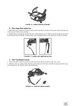
A bright spot is a small, non-uniform bright area that may flicker or appear constant (Figure 4-3).
Not all bright spots make the NYX-14 rejectable. Cup your hand over the lens to block out all light. If the 

bright spot remains please contact Customer Support. 

Bright spots usually go away when all light is blocked out. Verify that any bright spots are not simply the 

result of bright light in the area you are observing. Bright spots are acceptable if they do not interfere 

with the user’s ability to view the scene  or perform missions.  

Summary of Contents for NYX-14

Page 1: ...H during the follow ing 14 days for refund Shipping handling and EOC charges are non refundable Return shipping and insurance costs remain the responsibility of the customer All items returned for exc...

Page 2: ...ay cause allergic reactions The FDA has reported an increase in the number of deaths that are associated with an apparent sensitiv ity to natural latex proteins If you are allergic to latex it is a go...

Page 3: ...fore replacing the intensifier tube confirm that it is no longer covered by warranty Thoroughly dry each component of the NYX 14 before placing them in the storage case NOTES The equipment requires so...

Page 4: ...Standard Components 14 2 4 Optional Equipment 15 2 5 Key Features 17 3 OPERATING INSTRUCTIONS 18 3 1 Installation and Mounting 18 3 1 1 Battery Installation 18 3 1 2 Mounting the NYX 14 to a Goggle K...

Page 5: ...B Intensifier Tube Replacement Manual 36 C Product Warranty Registration Card 38 Alphabetical Index 39 LIST OF FigureS FIGURE TITLE PAGE 2 1 NYX 14 Night Vision Monocular 12 2 2 NYX 14 Standard Compon...

Page 6: ...rvices 27 4 2 Operator Troubleshooting 29 A 1 NYX 14 List of Spare Parts 35 HOW TO USE THIS MANUAL USAGE You must familiarize yourself with the entire manual before operating the equipment Before perf...

Page 7: ...YX 14 can be used as a handheld head mounted or helmet mounted to allow walking short range surveillance map reading vehicle maintenance and administering of first aid The NYX 14 allows for horizontal...

Page 8: ...ed below within the applicable warranty period The customer understands and agrees that except for the foregoing warranty no other warranties written or oral statutory expressed or implied including a...

Page 9: ...rchan dise returns that do not have an RMA listed may be refused or a significant delay in processing may occur Estimated Warranty service time is 10 20 business days The End user Customer is responsi...

Page 10: ...d IT Intensifier Tube L Length LED Light Emitting Diode lx lux m meter mA milliampere min minute mm millimeter mW milliwatt nm nanometer No Number NV Night Vision NVD Night Vision Device Para Paragrap...

Page 11: ...ination level low battery and to show the user that the IR illuminator is on The NYX 14 allows for vertical and fore and aft adjustment when mounted to the user s head or hel met when focusing the len...

Page 12: ...12 Turn pull Function Switch 5 Eye cup 13 Focus Ring 6 Battery Cap 14 Lens 7 Gain Control Knob 15 Lens Cap 8 Battery Compartment For NYX 14 M version 2 2 Specifications Table 2 2 Mechanical Data Equip...

Page 13: ...Battery 123A Lithium Battery 30 IT Gen 2 25 IT Gen 3 60 IT Gen 2 50 IT Gen 3 With IR illuminator off Table 2 4 Optical Data ITEM DATA Magnification with 1X Lens with 3X Lens with 5X Lens with 8X Lens...

Page 14: ...Operating Temperature 40 to 50 C Storage Temperature 50 to 70 C Humidity 95 25 C to 40 C for 48 hr Illumination Required Natural night illumination overcast starlight to moonlight Immersion 20 m for...

Page 15: ...ower the unit 6 Operation and Maintenance Manual Provides safety information equipment description mounting procedures operating instructions and preventive maintenance checks and service including a...

Page 16: ...their position becomes compromised ANEC000001 IR810 IR Illuminator Extra long range infrared illuminator Provides greater viewing capabilities when the environment has little or no ambient light IAIR...

Page 17: ...the NYX 14 and its accessories ANHC000001 2 5 Key Features Gen 2 3 intensifier tube Automatic bright light cut off system to protect the intensifier tube LED lights visible in the eyepiece viewing ar...

Page 18: ...he severe cold will adversely affect the life of the battery In these conditions it is recommended that you use a lithium iron disulfide 1 5V AA battery or its equivalent Install the CR123A battery as...

Page 19: ...goggle kit bracket Turn the unit around 180 and mount it on the bracket through the rail on the second side With the button E pushed move the unit along the slide rail F until the desired most comfort...

Page 20: ...n C and slide the unit out of the guide D C d E G B A Figure 3 3 MOUNTING THE NYX 14 TO A HELMET F A 3 1 4 MOUNTING THE NYX 14 TO A DUAL BRIDGE To install two NYX 14 units onto a single binocular devi...

Page 21: ...ve lens of the NYX 14 and screw in the 3X 5X or 8X lens in its place The NYX 14 configured with an 8X lens can be installed on a tripod To mount the unit on a tripod use the 1 4 threaded socket E on t...

Page 22: ...l axis of the NYX 14 with the camera objective Tight en the screws E and F 6 To focus the image loosen the screw G and adjust the distance between the monocular and the camera s eyepiece Tighten the s...

Page 23: ...position the unit is off ON position the unit is on IT powered Turn the unit on by turning the switch CCW from OFF to ON IR position the unit is on and the IR illuminator is activated Activate the IR...

Page 24: ...D LIGHT in the eyepiece viewing area indicates that the battery is low For NYX 14M version only 3 3 OPERATIng Procedures 3 3 1 Operating Procedures These procedures should be performed under nighttime...

Page 25: ...to 3m 1 To activate the IR illuminator turn the monocular on Pull the IR illuminator out and flip the turn pull function switch A CW from ON to the IR position A red light will appear in the eyepiece...

Page 26: ...tions in reverse 4 Unscrew the battery cap and take out the battery Replace the battery cap Do not store the unit with the battery still in it 5 Store the unit and all accessories in the case 3 4 Stor...

Page 27: ...e item to be checked or serviced Procedure column Details the checking servicing procedure Not Fully Mission Capable If column Indicates what faults will prevent your equipment from operating successf...

Page 28: ...ment Inspect optional items for dirt or corrosion damage and missing parts Check for proper operation If necessary clean as detailed in Part 4 4 2 Equipment is damaged or parts are missing OPERATIONA...

Page 29: ...nated If the IR illuminator fails to activate please contact Customer Support LED indicators fail to activate Visual inspection Please contact Customer Support Poor image quality Check objective lens...

Page 30: ...not normally a cause for returning the NYX 14 However some types of cosmetic blemishes can worsen over time and interfere with the user s ability to properly oper ate the device during missions If you...

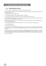
Page 31: ...interfere with the operator s ability to perform missions D Fixed pattern Noise Fixed pattern noise is usually a cosmetic blemish characterized by a faint hexagonal honeycomb pat tern that appears thr...

Page 32: ...rfaces except for glass surfaces with another clean soft dry cloth 4 Using a lens brush carefully remove all loose dirt from the glass surfaces 5 Slightly dampen a cotton swab with ethanol Gently and...

Page 33: ...e left side of the head band and threading the end of another strap into the corresponding buckle on the right side of the head band Figure 4 7 CHIN STRAP REinstallation C Chin Cup Replacement 1 Detac...

Page 34: ...rning the NYX 14 for service or repair the following procedures should be followed to pre vent any additional damage 1 Verify that the NYX 14 is free of all contaminants such as dirt or any other fore...

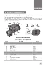
Page 35: ...ring specifications standards and inspection requirements 13 9 7 10 Figure A 1 NYX 14 Spare Parts 4 12 5 6 2 11 3 1 8 14 ALT TABLE A 1 NYX 14 LIST OF SPARE PARTS ITEM NO DESCRIPTION PART NO 1 Battery...

Page 36: ...or open wounds on the skin If the phosphor screen material contacts your skin wash it off immediately with soap and water If you inhale or swallow any phosphor screen material drink a lot of water ind...

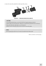
Page 37: ...ening the shipping container Treat the defective intensifier tube carefully to avoid damaging it further before returning it Only set the intensifier tube down on its contact end DO NOT force the inte...

Page 38: ...of the unit A c Product Warranty Registration Card In order to validate the warranty on your product EOC Company must receive a completed Product Warranty Registration Card for each unit or the user...

Page 39: ...ttent Operation 30 F number 13 Function Switch 12 23 G General Information 7 H Height 22 I IR Illumination Range 14 IR Illuminator 2 12 25 L Length 13 M Magnification 13 Maintenance 27 32 Goggle Kit 3...

Page 40: ...l rubber latex which may cause allergic reactions The FDA has noted an increase in the number of reported deaths that are associated with an apparent sen sitivity to natural latex proteins If you are...

Reviews: