background image

22

NSKW INSTALLATION MANUAL

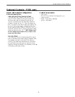
NSKWs come with a factory installed control board that is 

capable of receiving commands from the internal controller 

provided with the heat pump.  An alternative method is 

to control the heat pump using an external field supplied 

Aquastat or thermostat  that will turn the compressor on/off 

based on leaving water temperature.

When the heat pump is controlled by the internal controller 

it is called “Primary Mode” which allows the user to adjust 

the comfort level by adjusting temperature setting on the 

heat pump display.  For more information refer to panel 

configuration on standard controls.

An additional way of controlling the heat pump is by use of 

an external control such as an aquastat that gives a signal 

to the heat pump controlling to enable the compressor 

output.  This mode of control is referred to as “Secondary 

Mode” and requires components from an external field 

supplied source.   For more information on this control 

strategy refer to external control section of the manual. 

Heat Pump Control

IntelliStart

®

The optional IntelliStart single phase soft starter will reduce 

the normal start current (LRA) by 60%. Using IntelliStart 

also provides a substantial reduction in light flicker, reduces 

startup noise, and improves the compressor’s start behavior.

Summary of Contents for NSKW 06

Page 1: ...IM1066WN 05 15 Installation Information Water Piping Connections Electrical Data Startup Procedures Preventive Maintenance NSKW Installation Manual Geothermal Hydronic Heat Pump 50 Hz NSKW 06 to 17 kW ...

Page 2: ...21 Heat Pump Control 22 External Control 23 24 Converting to a Dedicated Cooling Unit 25 Unit Startup 26 Standard Board Control Features 27 28 Standard Control Panel Configuration 29 30 Optional Controls 31 35 Reference Calculations 36 Pressure Drop 36 Operating Limits 36 Flow Rates 37 Thermistor Resistance 37 Operating Parameters 38 Antifreeze Correction 39 Troubleshooting Guideline for Refrigera...

Page 3: ...ump 1 06 heating only models are available only with copper double wall vented load coax Vintage A 08 17 B 06 Future Option SS Standard Option Load Coax 1 C Copper N Cupronickel Source Coax C Copper N Cupronickel Controls Option 2 Standard Board 4 FX10 without communication 5 FX10 with Open N2 Com Card 6 FX10 with LonWorks card Com Card 7 FX10 with BACnet Com card 8 FX10 without communication with...

Page 4: ... 4 10 1 44 8 10 5 60 1 45 08 6 10 3 00 2 03 9 00 4 40 2 05 12 4 6 00 2 07 12 8 20 2 90 2 82 12 0 4 30 2 80 16 6 5 80 2 86 17 11 2 2 60 4 30 16 4 3 80 4 32 22 7 5 20 4 37 All ratings based upon 220V operation All ratings based on new heat pump with clean heat exchangers 9 26 11 Legend ABBREVIATIONS AND DEFINITIONS COP coefficient of performance EER cooling energy efficiency TC kW ELT entering load ...

Page 5: ... bill of lading to ensure that all crates and cartons have been received in good condition Examine units for shipping damage removing unit packaging if necessary to properly inspect unit Units in question should also be internally inspected If any damage is observed the carrier should make the proper notation on delivery receipt acknowledging the damage Units are to be stored in a location that pr...

Page 6: ...d Out HWG In HWG Out Power Supply Low Voltage Side Power Supply Side Power Supply Ext Pump Ext Pump Power Supply Power Supply 06 cm 6 1 6 1 6 1 6 1 8 9 7 4 37 8 6 6 5 3 4 4 7 4 10 4 08 cm 4 1 7 0 7 0 4 1 5 1 4 6 12 2 12 2 43 4 7 0 37 8 12 2 12 2 43 4 12 cm 4 6 9 1 9 1 4 6 5 3 4 6 12 2 12 2 43 4 7 1 37 8 12 2 12 2 43 4 17 cm 4 6 10 2 10 2 4 6 10 7 3 6 12 2 12 2 43 4 7 1 37 8 12 2 12 2 43 4 8 6 10 N...

Page 7: ...nia Chloride Less than 0 5 ppm Less than 0 5 ppm Less than 0 5 ppm Ammonia Nitrate Less than 0 5 ppm Less than 0 5 ppm Less than 0 5 ppm Ammonia Hydroxide Less than 0 5 ppm Less than 0 5 ppm Less than 0 5 ppm Ammonia Sulfate Less than 0 5 ppm Less than 0 5 ppm Less than 0 5 ppm Total Dissolved Solids TDS Less than 1000 ppm 1000 1500 ppm 1000 1500 ppm LSI Index 0 5 to 0 5 0 5 to 0 5 0 5 to 0 5 Iron...

Page 8: ...ng from use of a backup wrench For making the water connections to the unit a Teflon tape thread sealant is recommended to minimize internal fouling of the piping Do not over tighten connections All supply and return water piping should be insulated to prevent excess condensation from forming on the water lines NOTES 1 WaterFurnace recommends a male national pipe thread NPT to British standard pip...

Page 9: ...er capable of hot water generation HWG An optional factory installed hot water generator coil may be provided with NSKW08 17 The temperature of the hot water produced by the heat pump cannot be adjusted and will vary with the inlet temperature WaterFurnace recommends the use of a properly sized buffer tank equipped with supplemental electric immersion heaters in conjunction with all NSKW models us...

Page 10: ...WG Back Flow Preventer Pressure Relief Valve Source IN GEO STORAGE TANK PUMP HOT Piped in series to an electric water heater COLD DOMESTIC Dip Tube Ball Valve Vent Valve or P T Port Suggested Domestic Water Heater Hookup Potable Water Systems cont NOTES 1 Unions and valves must be installed so that acid flushing of the heat exchanger is possible 2 Route thermistor wires to NSKW Remove yellow therm...

Page 11: ...FLOW CENTER NOTES 1 Unions and valves must be installed so that acid flushing of the heat exchanger is possible 2 Make sure there is not a check valve in the diptube of the tank 3 Route thermistor wires to NSKW Remove yellow thermistor wires on TB 3 and 4 from control box and connect thermistor wires from geothermal storage tank Set the pump sampling PS in the set up of the control board to contin...

Page 12: ...es Most codes require backflow prevention check valves Note that a single check valve is not equal to a backflow prevention check valve Even if local code does not require this device WaterFurnace recommends its installation This is particularly important if the system will use antifreeze Pressure Reducing Valves or Feed Water Valves This valve lowers the pressure from the make up water line to th...

Page 13: ... guidelines for recommended flow and pipe sizing in the NSKW recommendations table WaterFurnace Geothermal Storage Tank Thermostat and Thermistor Yellow Thermistor Wires Connected to TB 3 and 4 on NSKW Control Board NSKW LOAD PUMP HYDRONIC LOAD Source OUT P T Ports P T Ports Ball Valve Dielectric Unions Dielectric Unions WaterFurnace NSKW Series NOTES A 207 kPa pressure relief valve Part No SRV30 ...

Page 14: ...ostat for Top Exit Lower Sensor Thermistor 12P541 01 to be used by Water to Water Units Optional From Geo Connection DIAMETER 20 3 cm 13 3 cm 90 8 cm Lower Thermostat DRAIN VALVE Model Number Gallon Liter Capacity Element Wattage 240 Volt Number of Elements R Value Dimensions in cm Approx Shipping Weight kg Height Diameter GEO STORAGE 80 80 303 4500 1 16 160 6 61 0 92 5 GEO STORAGE 120 119 450 450...

Page 15: ...ce Pump FLA Total Unit FLA Min Circ Amp Max Fuse HACR MCC RLA LRA LRA 06 220 240 50 1 198 264 17 5 11 2 60 0 24 0 1 5 4 5 17 2 20 0 30 380 420 50 3 342 462 6 5 4 2 28 0 16 8 4 2 5 3 6 08 220 240 50 1 198 264 27 0 17 3 97 0 34 0 1 5 4 5 23 3 27 6 40 380 420 50 3 342 462 10 0 6 4 45 0 27 0 6 4 8 0 10 12 220 240 50 1 198 264 31 5 20 2 126 0 44 0 1 5 4 5 26 2 31 2 50 380 420 50 3 342 462 12 1 7 8 51 5...

Page 16: ...ower sources to the unit 2 Remove the unit s top panel 3 Cut all plastic wire ties to the following a High pressure switch black wires b Low pressure switch blue wires c Freeze sensing yellow wires d Load temperature sensor black wires e Compressor wires 4 Remove the four screws from the control box 5 Relocate the control box to opposite end of the unit 6 Using the screws removed in step 4 above r...

Page 17: ...R T T RT ELT Orange X1 ELT ELT RT RT X2 X1 X1 ELT ELT RT RT X2 X1 RV Reversing Valve output ELT Entering Load Side Water Temperature Green Yellow T Thermistor P1 P2 P3 X3 X3 X3 X3 LPR Interface Panel Black Black Yellow Yellow Violet Violet Orange Orange Gray Gray 1 2 3 4 5 6 7 8 TB 1 1 G Load Pump External X2 X2 PS1 RVRVG RT Refrigerant Liquid line Temperature SI SI Slave Input relay R C Y1 O X1 G...

Page 18: ...ack Yellow Violet Violet Orange Orange Gray Gray 1 2 3 4 5 6 7 8 TB 1 1 G Load Pump External X2 X2 PS1 RVRVG RT Refrigerant Liquid Line Temperature SIR SIR Slave Input Relay R C Y1 O X1 G External SI RC Reversing Valve Coil Fuse Cap 9 10 11 12 1 Taped and wire tied off 2 3AG 10 Amp fuse 3 Move jumper wire to 5 and 6 for reversible secondary unit 4 Black Thermistor Source Coax Blue Thermistor Load ...

Page 19: ...r T SFS Source Flow Proving Switch LFS Load Flow Proving Switch TB Terminal Board RV Reversing Valve coil LP Low pressure switch HP High pressure switch ELT Entering Load Water Temp ES Emergency Shutdown CP Compressor Proving Compressor contactor CC LFD Load Freeze Detection Source Freeze Protection SFP LLT Leaving Load Water Temp EST Entering Source Water Temp LST Leaving Source Water Temp Legend...

Page 20: ...r Proving Switch SF Source Flow Proving Switch O Rev Valve Y1 Comp 1 SHC Secondary Unit Heat Cool SE Secondary Unit Enable LV Load Valve Output L Alarm X1 Acc 1 X2 Acc 2 PO Primary Load Over ride Output SN Secondary 24VAC Input R 24VAC LF Load Flow Proving Switch POI Primary Load Over ride Input C 24V COM TB Field Connection Diagram For units using Set Point control mode with or without a secondar...

Page 21: ...isplay For more information refer to panel configuration on standard controls An additional way of controlling the heat pump is by use of an external control such as an aquastat that gives a signal to the heat pump controlling to enable the compressor output This mode of control is referred to as Secondary Mode and requires components from an external field supplied source For more information on ...

Page 22: ...itioned across terminals 6 and 7 factory default set to this position Reversible units do not have a secondary output NOTES SL in the configuration menu must be set to 0 factory default All parameters should be checked for each application on primary unit refer to the parameter table Secondary Mode In dedicated heating or cooling units secondary mode allows the unit to be controlled by an external...

Page 23: ...ill immediately shutdown WARNING Do not stage more than 6 units C G W1 L X1 Y2 O Y1 W2 S X2 R C G W1 L X1 Y2 O Y1 W2 S X2 R C G W1 L X1 Y2 O Y1 W2 S X2 R Wiring for Primary Secondary Unit Staging First Stage Second Stage Third Stage NOTES X1 Secondary output Y1 Compressor call Staging with Aquastat When staging units using an Aquastat all units must be setup as secondary units WARNING Do not stage...

Page 24: ...In Then connect the Source Water Out line to the port marked Load Water Out 12 Connect the Load Water In line to the port marked Source Water In Then connect the Load Water Out line to the port marked Source Water Out Control Board with Jumper P4 P5 Key Pad Interface P9 Not Used P2 P1 13 Open the control box 14 Find the connection marked P4 as shown in the Control Board with Jumper illustration 15...

Page 25: ...Extraction on the source side in heating Heat of Rejection on the source side in cooling To ensure proper operation compare these values to the HE HR tables 8 Press the down arrow on the keypad to reduce the set point below the incoming load temperature Compressor should shut off and the load pump should shut off 30 seconds after the compressor 9 Wait 7 minutes The load pump should start to sample...

Page 26: ...djustable and fixed at 5 F Continuous Pump Mode C If continuous pump mode PS C In Service Menu is selected the control will respond immediately to a recognized call or termination of call for heat or cool subject to minimum run times and anti short cycle delays Test Mode Connection of a jumper wire from chassis ground to P3 will place the control in the test mode This shortens most timing delays f...

Page 27: ...r and pump operation will be disabled when the control senses that the freeze detection probe is open or has infinite resistance The LED display shall read dO Standard Board Control Features cont Freeze Detection Probe Closed dC Compressor and pump operation will be disabled when the control senses that the freeze detection probe is closed or has no resistance The LED display shall read dC Brown O...

Page 28: ...til the LED screen displays LC 2 Press the UP or DOWN arrow until 50 is displayed 3 Press the MODE button The screen should display SC to indicate the controller is in configuration mode 4 Once in configuration mode press the UP or DOWN arrow to scroll through the menu 5 Press the MODE button to enter the parameter Refer to the parameter table below for a list of configurable parameters 6 Once in ...

Page 29: ... is the closed loop setting which is 15 F 10 C P is the process setting which is 5 F 15 C 32 F P CL OL N A SL Primary Secondary Setting Primary mode utilizes an internal aquastat to determine the activity of the compressor In secondary mode the compressor output is determined by an external aquastat 0 Primary 0 or 1 1 Secondary 0 Primary IC Initial Condition This parameter is used to determine the...

Page 30: ...ware can be customized for specific projects Optional Medium User Interface MUI can be used as a field service tool Standalone FX10 Control functions as both unitary heat pump control and DDC communication therefore detail operational and fault information is available to BAS Other features are same as FX10 with addition of Johnson Controls N2 compatibility Same as FX10 with Johnson Controls N2 BA...

Page 31: ...abled Freeze Detection Temperature Limit Field selectable for 9 4 or 1 1 C Installation Options Standalone controlled by standard aqua stat Integrated into BAS by adding communication module Accessory Outputs Quantity 2 Cycled with the compressor Field selectable for normally open factory default or normally closed through the building automation system or user interface User Interface 4 x 20 back...

Page 32: ...ockout at disconnect or through BAS 2 Accessory outputs Optional BAS add on controls DDC Operation and Connection Other optional network protocol boards that can be added to the FX10 are Johnson Control N2 LonWorks BACnet MS TP 19 200 Baud rate Limit devices to 30 on a single trunk line Control and Safety Feature Details Emergency Shutdown The emergency shutdown mode can be activated by a command ...

Page 33: ...d to 5 seconds and the reversing valve will be allowed to cycle without shutting down the compressor If an MUI is connected to the control LED 8 will flash and the words Test Mode Enabled will be shown on the LCD display when the control is in test mode Test mode will be disabled after a power cycle 30 minute timeout or by holding the ESC and Up arrow keys on the MUI Sequence of Operation Power Fa...

Page 34: ... factory set for 1 1 C When the jumper on BI 4 is removed the source freeze detection setpoint will be 9 4 C NOTE Piping circuit must be antifreeze protected to the set levels or the warranty will be voided Accessory Output The Accessory Outputs will be energized 90 seconds prior to the compressor output being energized When the compressor output is turned off the accessory outputs will be deactiv...

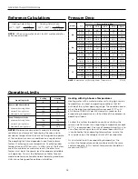
Page 35: ...1 1 6 7 Normal Entering Water 29 4 15 6 Maximum Entering Water 43 3 32 2 Load Side Water Limits Minimum Entering Water 10 0 15 6 Normal Entering Water 15 6 37 8 Maximum Entering Water 32 2 48 9 NOTES Minimum maximum limits are only for startup conditions and are meant for bringing the space up to occupancy temperature Units are not designed to operate at the minimum maximum conditions on a regular...

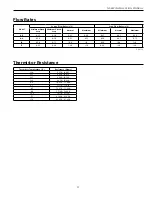
Page 36: ...32 270 33 690 0 8 33 190 34 940 16 9 79 110 83 750 17 5 81 860 86 460 17 8 82 960 87 860 Thermistor Resistance Model Source Flow Rates L S Load Flow Rates L S Minimum Open Loop Minimum Closed Loop Normal Maximum Minimum Normal Maximum 06 0 25 0 30 0 45 0 60 0 25 0 45 0 60 08 0 30 0 50 0 65 0 75 0 30 0 65 0 75 12 0 50 0 75 1 00 1 10 0 50 1 00 1 10 17 0 65 0 90 1 20 1 30 0 60 1 20 1 30 2 14 12 ...

Page 37: ...0 3199 3447 3 9 3 9 10 731 883 3268 3551 3 9 3 8 20 862 1076 3344 3654 3 9 2 8 30 operation not recommended 9 26 11 Cooling Mode Entering Load Temp C Entering Source Temp C Suction Pressure kPa Discharge Pressure kPa Superheat C Subcooling C 10 0 593 683 931 1103 7 12 1 8 10 634 738 1317 1475 6 11 2 8 20 676 793 1710 1848 3 8 3 9 30 696 820 2310 2530 3 8 4 9 45 724 841 2930 3206 4 9 6 11 20 0 614 ...

Page 38: ...3 1 419 Propylene Glycol 10 0 981 0 958 0 959 0 981 1 130 20 0 967 0 913 0 921 0 969 1 270 30 0 946 0 854 0 869 0 950 1 433 40 0 932 0 813 0 834 0 937 1 614 50 0 915 0 770 0 796 0 922 1 816 Ethanol 10 0 986 0 927 0 945 0 991 1 242 20 0 967 0 887 0 906 0 972 1 343 30 0 944 0 856 0 869 0 947 1 383 40 0 926 0 815 0 830 0 930 1 523 50 0 907 0 779 0 795 0 911 1 639 Methanol 10 0 985 0 957 0 962 0 986 1...

Page 39: ... Flow Cooling High High High High Low High High Air Flow Heating Low Low Low Low High Low High Air Flow Cooling Low High Normal High Low Normal High Water Flow Heating Normal Low Normal High Normal Low High Water Flow Cooling Low Low Low Low High Low Low Indoor Air Temperature Heating Low Low Low Normal High Normal High Low Indoor Air Temperature Cooling Low Low Low Normal Low High Low High Indoor...

Page 40: ...ering Load Water C Entering Load Water Pressure kPa Leaving Load Water C Leaving Load Water Pressure kPa Load Coax Suction Discharge Compressor RV Source Coax FD ______kPa ______SAT C ______ C ______kPa ______SAT C ______ C ______ C Liquid Line Load Coax Unit Amp Draw Line Voltage Loop Open Closed Subcooling Superheat NOTE Do not attach refrigerant gauges unless a problem is suspected Entering Sou...

Page 41: ... n _____ AMPS n ______ AMPS n ______ AMPS Watts m x n x 0 85 o _____ WATTS o ______ WATTS o ______ WATTS 6 CAPACITY Cooling Capacity HR o p _____ kW hr Heating Capacity HE o p _____ kW hr 7 EFFICIENCY Cooling EER p o q _____ COP Heating COP p o q _____ COP 8 SUPERHEAT S H SUBCOOLING S C COOLING HEATING HYDRONIC Suction Pressure r ______ kPa r ______ kPa r ______ kPa Suction Saturation Temperature ...

Page 42: ...otection may be open If the compressor dome is extremely hot the overload will not reset until cooled down If the overload does not reset when cool it may be defective If so replace the compressor 9 The internal winding of the compressor motor may be grounded to the compressor shell If so replace the compressor 10 The compressor winding may be open Check continuity with an ohm meter If the winding...

Page 43: ...tion is secure replace the thermistor Troubleshooting Controls Check the unit If a lockout mode is displayed refer to the table below to determine the meaning of the failure Follow the procedure listed to correct the problem Check the mode 1 If the unit is running on the internal aquastat verify the unit is in Primary mode The SL should be set to 0 in the setup menu 2 If the unit is running on an ...

Page 44: ...gallon pail refer to the Cleaning Connections illustration 5 Connect a plastic hose from the inlet line of the water to refrigerant heat exchanger to the plastic pail Secure tightly to ensure that circulating solution does not spill refer to the Cleaning Connections illustration 6 Partially fill the plastic pail with clear water about two thirds full and prime the circulating pump Circulate until ...

Page 45: ...P505 05 Electrical Compressor Contactor Single Phase 13P004A03 13P004A03 13P004A03 13P004A03 Compressor Contactor Three Phase 13P537B03 13P537B03 13P537B03 13P537B03 Transformer 220 240v 15P501 02 15P501 02 15P501 02 15P501 02 Transformer 380 420v 15P511 02 15P511 02 15P511 02 15P511 02 Connection Block 3 Position 12P503 06 12P503 06 12P503 06 12P503 06 Connection Block 12 Position 12P503 07 12P50...

Page 46: ...Revision Table Pages Description Date By All Updated Nomenclature Electric Heating Data Service Parts List and Physical Data 05 May 2015 MA All Revision table added 05 May 2015 MA ...

Page 47: ...duct Envision NSKW Type Geothermal Hydronic Heat Pump 50 Hz Size 06 17 kW Document Installation Manual 2015 WaterFurnace International Inc 9000 Conservation Way Fort Wayne IN 46809 9794 WaterFurnace has a policy of continual product research and development and reserves the right to change design and specifications without notice ...

Reviews: