Enviro EG-40 Owner'S Manual Download Page 9

VERTICAL INSTALLATION 

 
STEP 1.  Check the instructions for required clearances (air spaces) to combustibles when passing through ceilings, walls, 

roofs, enclosures, attic rafters, or other nearby combustible surfaces. Do not pack air spaces with insulation. 

 
STEP 2.  Set the gas appliance in the desired location. Drop a plumb bob down from the ceiling to the position of the appliance 

flue exit, and mark the location where the vent will penetrate the ceiling. Drill a small hole at this point. Next, drop a 
plumb bob from the roof to the hole previously drilled in the ceiling, mark the spot where the vent will penetrate the 
roof. Determine if ceiling joists, roof rafters, or other framing will obstruct the venting system. You may wish to 
relocate the appliance, or to offset, to avoid cutting load bearing members. 

 
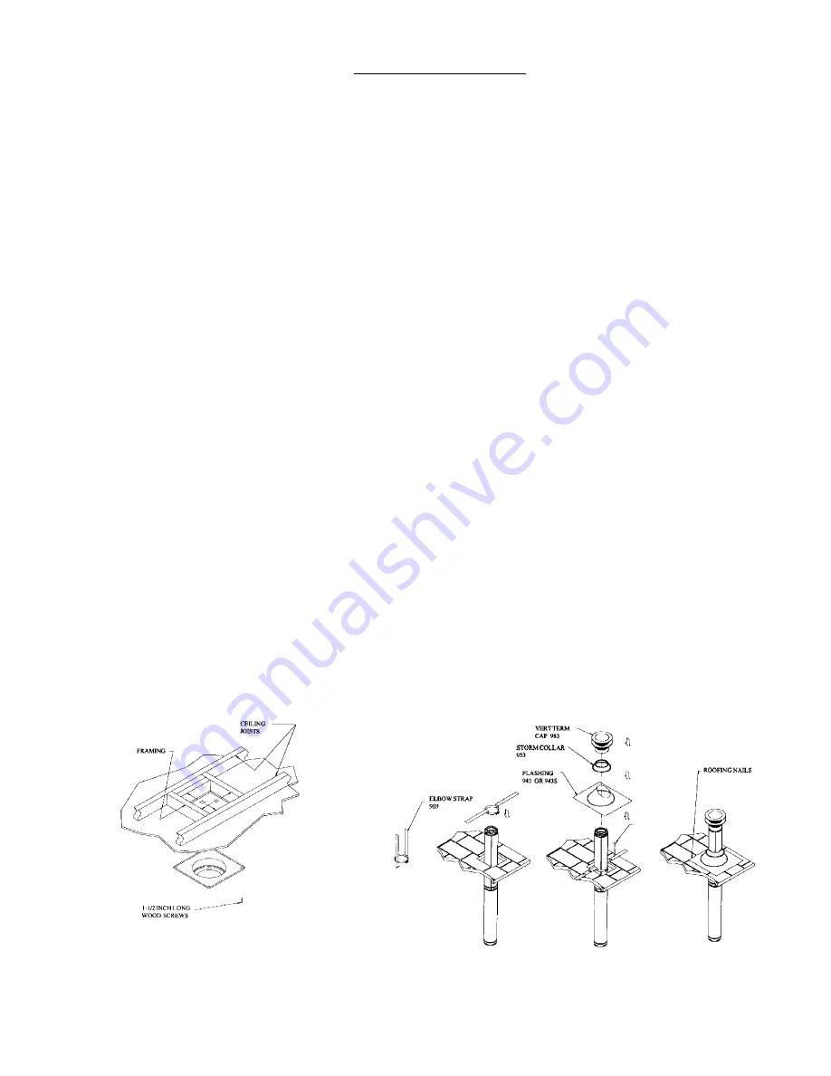
STEP 3.  To install the Round Support Box/Wall Thimble in a flat ceiling, cut a 10- inch square hole in the ceiling, centered in 

the hole drilled in Step 2. Frame the hole as shown in FIG-16. 

 
STEP 4.  Assemble the desired lengths of black pipe and elbows necessary to reach from the appliance adapter up through 

the Round Support Box. Insure that all pipe and elbow connections are in their fully twist-locked position. 

 
STEP 5.  Cut hole in the roof centered on the small hole placed in the roof from Step 2. The hole should be of sufficient size to 

meet minimum requirements for Clearance to Combustibles, as specified. Continue to assemble lengths of pipe and 
elbows necessary to reach from the ceiling Support Box up through the roofline. Galvanized pipe and elbows may be 
utilized in the attic, as well as above the roofline. The galvanized finish is desirable above the roofline, due to the 
higher corrosion resistance. 

 
STEP 6.  Once the pipe sections have been joined, and run up through the hole in he roof, slip an elbow strap (Part-989) over 

the exposed sections, bend the support straps outwards, and push the Elbow Strap down to the roof level, as shown 
in FIG 17. Tighten the clamp around the Pipe section. Use a level to make sure the pipe is truly vertical. With roofing 
nails, secure the support straps to the roof. Seal the nails holes heads with non-hardening mastic. Trim the excess 
length of the support straps that extend out beyond the edge of the flashing. 

 
STEP 7.  Slip the flashing over the pipe section protruding through the roof. Secure the base of the flashing to the roof with 

roofing nails. Use a non-hardening sealant between the uphill edge of the flashing and the roof. Insure the roofing 
material overlaps the top edge of the flashing as shown in FIG 17. Verify that you have at least the minimum 
clearance to combustibles at the roofline. 

 
STEP 8.  Continue to add pipe sections until the height of the vent cap meets the minimum code requirements. FIG 22. Note 

that for steep roof pitches, the vent height must be increased. In high wind conditions, nearby trees, adjoining roof 
lines, steep pitched roofs, and other similar factors can result in poor draft, or down drafting. In these cases, 
increasing the vent height may solve the problem. 

 
STEP 9.  Slip the Storm Collar over the pipe, and push it down to the top of the roof flashing as shown in FIG 17. Use the non-

hardening sealant around the joint between the pipe and the Storm Collar. 

 
STEP 10. Twist - lock the vent cap. 


  FIG-16 


      FIG-17 


9

Summary of Contents for EG-40

Page 1: ...on may result causing property damage personal injury or loss of life installation and service must be performed by a qualified installer service agency or the gas supplier Do not store or use gasolin...

Page 2: ...tallation must conform to local codes or in the absence of local codes with the current CAN1 B 149 installation code in Canada or the current National Fuel Gas Code ANSI Z223 1 in the USA To prevent i...

Page 3: ...IGH ALTITUDE SPECS ENVIRO EG 40 DIRECT VENT UNITS Have all been certified for use with either natural or propane gases See control panel and rating label Are not for use with solid fuels Must not be c...

Page 4: ...aintenance Locate a position where the flue system of the stove can be properly installed without damaging the integrity of the building E g cutting a wall or ceiling joist The stove can be installed...

Page 5: ...inimum K Clearance to a mechanical air supply inlet 6 feet 1 8m minimum L Clearance above paved side walk or paved driveway located on public property 7 feet 2 1m minimum M Clearance under verandah po...

Page 6: ...PERMITTED TO REACH THE OUTSIDE VENT TERMINATION BEFORE BEGINNING THE INSTALLATION TAKE CARE TO ENSURE AN APPROPRIATE OUTSIDE LOCATION FOR THE VENT TERMINATION CAN BE ACCOMMODATED FOLLOW THE VENT LENG...

Page 7: ...dentations located on the female end of the pipes and fittings are designed to slide straight onto the male ends of adjacent pipes and fittings by orienting the four pipe indentations so they match an...

Page 8: ...nts excessive heat from possibly melting the vinyl siding material Note that the horizontal vent termination bolts onto the flat portion of the vinyl siding standoff Shaded area in FIG 12 so that an a...

Page 9: ...pipe and elbows may be utilized in the attic as well as above the roofline The galvanized finish is desirable above the roofline due to the higher corrosion resistance STEP 6 Once the pipe sections h...

Page 10: ...t the second floor and any subsequent floors FIG 19 The opening should be framed to 10 inch x 10 inch inside dimensions in the same manner as shown in FIG 16 2 Any occupied areas above the first floor...

Page 11: ...ide on a location for the unit that will meet any or all local code requirements Refer to sections in this manual Deciding Were To Locate Your Stove and Planning Your Installation Set the appliance in...

Page 12: ...liner over collar secure the flex liner with 3 sheet metal screws evenly spaced Align all straight sections of pipe slipping all joints together and installing 3 sheet metal screws evenly spaced A sm...

Page 13: ...nimum 4 flex liner to the top of the CLASS A chimney Placing a bead of high temperature silicone to the Simpson Cap adapter and securely attach the flex liner to the adapter Secure the cap adapter to...

Page 14: ...t is very important to install these logs in their correct position to insure safe optimum operating conditions Open the door of the fireplace Place the logs on the log supports Close the door and tig...

Page 15: ...f all electrical power to the appliance 3 Turn the gas control knob clockwise to the off position 4 Open door Wait five 5 minutes to clear out any gas Close door If you smell gas including near the fl...

Page 16: ...first 4 hours of use See page 14 After that depending upon the amount of use cleaning should be required no more than two or three times per season To clean the door use a mild glass cleaner and a so...

Page 17: ...d Bleed line Check gas line pressure Contact dealer Burners will not remain lit Problem with thermopile circuit Check gas line pressure Check for flame impingement on thermopile if low see Pilot will...

Page 18: ...the current edition of the National Fuel Gas Code ANSI Z223 1 UPON CONNECTION MARK APPROPRIATE FUEL TYPE ON WARNOCK HERSEY RATING LABEL LOCATED ON THE INSIDE OF THE RIGHT HAND SIDE PANEL Manifold Pres...

Page 19: ...ly to the floor WARNING ELECTRICAL GROUNDING INSTRUCTIONS This appliance is equipped with a three prong grounding plug for your protection against shock hazard and should be plugged into a properly gr...

Page 20: ...Voltage Thermostat REMOVING THE BLOWER 20 1 Turn the unit off and remove the log set 2 Remove the burner tray assembly by removing the screw on either side of the tray between the front and rear burne...

Page 21: ...lot orifice First remove the two 2 T 20 Torx screws that hold the pilot assembly to the burner tray Lift the pilot assembly from the burner tray Using a 10mm wrench disconnect the pilot line from the...

Page 22: ...ts only thereafter The paint on the Metal Brick Liner may peel This is due to the extreme conditions applied to the paint and is no way covered under warranty Your dealer shall make all claims under t...

Page 23: ...g Harness Complete 2 pieces 30 014 Freestanding Burner Control NG Complete EC 040 Freestanding Fan Control Knob 30 015 Freestanding Burner Control LP Complete EC 043 IEC Power Cord 30 017 Rear Burner...

Page 24: ...r 2003 EG40 GAS TRAY AND DOOR ASSEMBLIES Rear Venturi EG40 099 S I T Nova 820 Valve EC 006 NG EC 007 LPG S I T Piezo Ignitor EC 023 Burner Switch EC 025 Light Switch EC 066 FS Fan Controller EF 045 FS...

Page 25: ...ing Side Panel Cabinet EG40 086 Flue Pipe Freestanding Pedestal Wiring Plate Freestanding Pedestal Box Cover EG40 307 1x1 Side Cabinet Hinge EC 054 Freestanding Side Panel Cabinet EG40 086 Convection...

Page 26: ..._________ Name of Installer ___________________________________________ Address _______________________________________ ___________________________________________ ____________________________________...

Reviews: