background image

Users manual 

 FA845  

version 1.5 

Envionic 

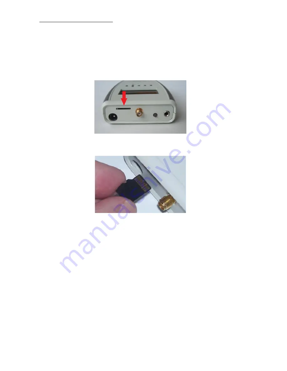
1.2  Micro-SD memory card 


The micro-SD memory card should only be placed or removed when the device is switched 
off. The card should be placed with its contacts pointing upwards to the top of the device . 
You can use your nail to push it the last stretch until it clicks.  


Position of the micro-SD memory card


Contacts of the card pointing upwards 


Summary of Contents for FA720

Page 1: ...Users manual FA845 version 1 5 Envionic 1 Field Analyzer FA845 Users Manual Also for the FA720 FA725 FA730 and FA735 www envionic com...

Page 2: ...hapter 3 RF SCAN mode 21 3 1 Spectrum analyzer introduction 21 3 2 SCAN Display 22 3 3 SCAN Frequency bands 23 3 4 SCAN Peak display 24 3 5 Other functions in SCAN mode 25 3 6 Single frequency measure...

Page 3: ...1 5 Envionic 3 7 3 View measurements with your computer 45 Appendices 46 Appendix 1 Specifications FA845 46 Appendix 2 Conversion from microwatt m to milliVolt meter 47 Appendix 3 More information 48...

Page 4: ...me mode you can view these pulses on the screen The spectrum analyzer can measure very low field strengths and their frequency The figures measured are displayed on a clear graphic LCD display The low...

Page 5: ...WLAN or WIFI wireless computer networks WIMAX wireless network wireless video systems microwave ovens bluetooth wireless systems television transmitters 2 Low frequency electric fields FA 730 735 845...

Page 6: ...card to the USB port of your computer The memory card and cardreader are only delivered with the FA725 FA735 and FA845 Two AA Alkaline batteries or optional two NiMH rechargeable batteries Optional ch...

Page 7: ...screen as long as the device is switched on On the screen you will see the model number FA845 FA735 FA730 FA725 or FA720 software version Image V 2 0 and serial number 0504 of the device This manual...

Page 8: ...should only be placed or removed when the device is switched off The card should be placed with its contacts pointing upwards to the top of the device You can use your nail to push it the last stretch...

Page 9: ...n choose what you want to measure Push the 1st button RF to measure the high frequency electromagnetic field chapter 2 Push the 2nd button Elec to measure the low frequency electric field chapter 5 Pu...

Page 10: ...After some practice it is possible to identify the kind of radiation by the sound it produces The strength of the radiation has not much influence on the sound volume unless the signals are very weak...

Page 11: ...n the screen At first as a partly filled battery see picture After some time the filling in the battery picture will blink When the battery can no longer be used an empty battery symbol will blink Aft...

Page 12: ...ies are being charged then switch the device on You will see an animated picture of a battery that that is being filled Then you can switch the device off again If you keep the meter on while the batt...

Page 13: ...on becomes available it can be sent to you by email The following steps must be followed to install new software 1 Switch your device OFF and remove the memory card 2 Put your memory card in the cardr...

Page 14: ...lected by big objects indoor or outdoor objects The combination of direct and reflected signals causes interference patterns Due to interference the measured value can vary a lot even when the device...

Page 15: ...enuated while travelling through your body Most signals have a vertical polarization Due to this a vertical position of the device and antenna is optimal when using the non directional antenna Signals...

Page 16: ...trength of the signal in microwatt per square meter When the signal is pulsed the shown strength is the strength at the top of the pulse The frequency of all signals is measured if possible and the fr...

Page 17: ...you can also see small signals while strong pulses of another frequency are present Above the signal with the highest strength you will see a small arrow and the corresponding frequency category is vi...

Page 18: ...Choosing the measurement unit Within the Hold function group you will als find the Unit button button 2 Here you can change the measurement unit of the device you can choose between microwatt per squa...

Page 19: ...will now see Time instead of GHz Pressing button 2 again it is now called Freq will switch back to the normal display The following example shows the pulses of a DECT base station The dotted line is t...

Page 20: ...g sleep according to the German SBM2015 standard Also the values with qualification slight concern severe concern and extreme concern will be visible This only works in the microwatt per square meter...

Page 21: ...een given two major operating modes 1 SCAN described in this chapter In the SCAN mode the user selects the frequency band that he wants to measure It is selected from a fixed list of bands The START a...

Page 22: ...nd Stop frequencies 925 and 960 MHz for GSM900 D The dotted line shows the position of the strongest signal E Indicates that button 3 selects the previous frequency band F Indicates that button 6 sele...

Page 23: ...nd is shown as an arrow pointing upwards EU means that this is a frequency band used in Europe in the USA and some other countries the band frequencies are slightly different In the described software...

Page 24: ...1 5 Envionic 24 3 4 SCAN Peak display A dotted line D will show the position of the strongest signal called Peak The frequency of the strongest signal is shown at the left side of the screen B and th...

Page 25: ...see next section B The marker function lets you control the dotted line by using left and right buttons The frequency at the marker position is shown at the left side of the screen and the strength a...

Page 26: ...es strongly every second in SNGL mode this means that this is a mirror image frequency A mirror image frequency is an unwanted signal that is not really present at the specified frequency The device a...

Page 27: ...in the next diagram where the antenna has been disconnected to remove the signal You see that the display shows 00001 the actual level with disconnected antenna If you select HOLD and switch it from o...

Page 28: ...fter the last frequency band the file must end with with The description will be shown on the screen of the device as 3 rows of maximal 4 characters When a row starts with U or D followed by a space t...

Page 29: ...and list file select it from the Home screen by selecting Menu and then Card Then select the xxxxxxx ini file and press Open This will load the file in the device This must be done each time after swi...

Page 30: ...N mode to EXPERT mode select Disp with button 4 and then use button 2 Xprt 4 1 XPRT Display In the XPRT mode you will see the following screen At the left side of the screen there is no band informati...

Page 31: ...the center frequency up or down in half SPAN steps using left and right buttons Button 1 Select CF center freq mode or PK peak freq mode Button 2 Set CF to PK frequency C MKR Move the dotted line mark...

Page 32: ...F B will switch back to the first intermediate frequency A real signal will be visible at the same frequency for both values of the intermediate frequency But a mirror image will only be visible at on...

Page 33: ...P 900 The CF center frequency has changed from 700 to 800 MHz The frequencies in the picture do not match this example In FREQ and SPAN modes you can use button 1 to toggle the indication between Peak...

Page 34: ...the following screen The first 3 buttons can be used to enter the digits that are in a box 1 2 or 3 here A The backarrow removes the last entered digit B The up down buttons move the row of boxes up o...

Page 35: ...CF center frequency will stay the same Example Suppose START 600 STOP 800 so SPAN 200 If you decrease the SPAN from 200 to 100 MHz you will get START 650 STOP 750 so SPAN 100 The center frequency 700...

Page 36: ...ress button 1 and keep it pressed during one second this gives you the following screen Now pressing Num will let you enter the From START frequency After entering the start frequency press button 1 a...

Page 37: ...uch too low The device should be grounded by placing one of your fingers at the grounding point at the backside of the device Grounding point The device responds to changes in the surrounding electric...

Page 38: ...adjusted for optimal visibility The range is 0 5 V m up to 199 V m After switching the device on it will take 20 seconds before the electric field can be measured If you choose Hold switch this on as...

Page 39: ...to the normal display For indoor living or working areas you can use values that are 10 times higher than the values during sleep that are shown here 5 4 Orientation for older devices In older devices...

Page 40: ...everal position because it is only sensitive to a single direction of the magnetic field lines The highest measured value should be used The device should not be moved during the measurement Magnetic...

Page 41: ...e Safe you will see together with the measured value what values are safe for the magnetic field strength during sleep according to the German SBM2015 standard Also the values with qualification sligh...

Page 42: ...ent day Measurements of one day In the top line you see the year month date and the day of the week Choose the kind of measurements that you want to see with button 6 for instance RF uW m The logged R...

Page 43: ...lue 160 The starting time of the chosen time period is shown at the top left corner of the screen in the example october 22 12 00 The frequency category that belongs to the choosen time period is at t...

Page 44: ...upwards It will fit in two ways but it will work in only one way As soon as the cardreader is attached to the PC a window will pop up Choose Open folder to view files Then choose the folder Log and t...

Page 45: ...rows Cell G10 up to R10 indicate the frequency category of the cells below them In this example several columns are deleted between column H and I to get a clearer picture The first frequency categor...

Page 46: ...f pulsed signals Hold function for remembering the highest peak value SMA connector for external antenna Antenna for 700 MHz 6 GHz is included Low frequency Low frequency electric field from 0 5 V m u...

Page 47: ...00 2 500 900 2 000 800 1 600 700 1 250 620 1 000 560 800 500 630 450 500 400 400 350 320 320 250 280 200 250 160 220 125 200 100 180 80 160 63 140 50 125 40 110 32 100 25 90 20 80 16 70 12 5 62 10 0 5...

Page 48: ...potential difference mV milliVolt 0 001 Volt W Watt Unit for power energy per second W microWatt 0 000001 Watt DECT Digital Enhanced Cordless Telephone GSM Global System for Mobile Communications TET...

Reviews: