background image

Then the 

network unlocking

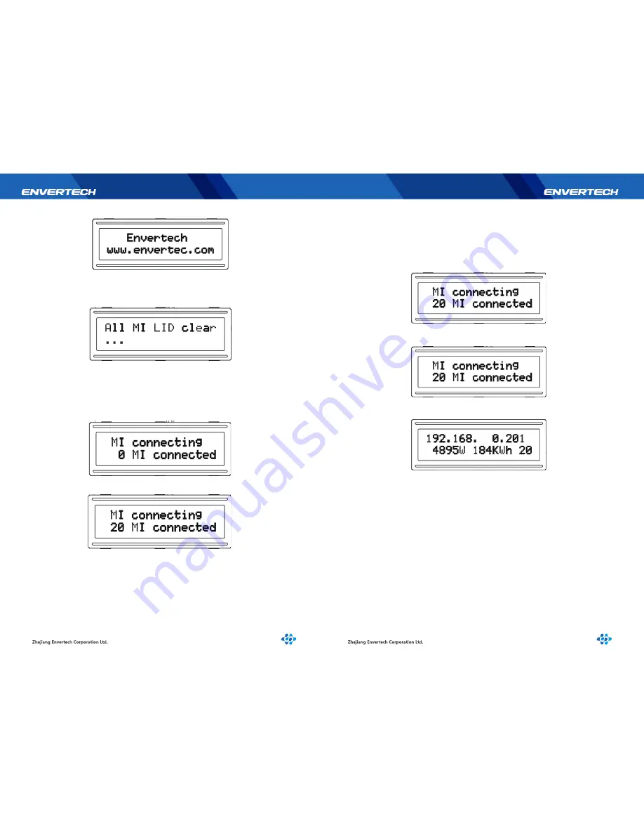
 starts and on the screen of LCD “All MI LID clear” shows 

on the first line and “...”on the second line, which indicates the overall 

network 

unlocking

 process is taking place (as shown below).

Upon the completion of the overall network 

unlocking

 the 

network construction


between  EnverBridge  and  MI  starts.  On  the  first  line  of  the  LCD  1602  screen “MI 

connecting” indicates the connection to MI has started and “x MI connected” on the 
second line shows how many MI units have been connected with x indicating the 
numbers of MI units connected.

EnverBridge gets into monitoring working status following the starting-up of Enver-

Bridge. The  monitoring  information  will  be  displayed  on  LCD,  which  includes  four 

parts, namely, IP address, the current power, power production and the numbers of MI 

units (as shown below).

IP address shows on the first line of LCD screen. For example, 192.168.0.201 indicates 
a  normal  network  connection  and  192.160.0.254  indicates  an  abnormal  network 

connection.
The figure of power efficiency which shows at the beginning of the second line 
indicates the real-time power efficiency. For example, 4895W.
The figure of power generation output which shows at the middle of the second line 

indicates the overall amount of power generation. For example, 184KWh or 100MWh  

The power generation output is calculated to the accuracy of KWh. If the output rises 
up to MWh ,the number displayed is 

rounded off automatically

. (Please refer to the 

long distance or local server to get a detailed information.)

After the completion of network construction the EnverBridge start-up process 
finishes and EnverBridge is in normal monitoring working status. It will take a 
relatively long period of time before the monitoring interface information shows up 

on  the  LCD  screen.  EnverBridge  will 

unlock

 and 

construct the network

 again 

automatically if there is a failure of network construction.

13

14

6.3 Monitoring interface

6.4 Making-up network construction status

Summary of Contents for EnverBridge

Page 1: ...er Operating Manual Model Number EnverBridge This manual is an integral part of the unit Please read the instruction manual carefully before installation operation or maintenance Keep this instruction...

Page 2: ...id Connection 5 3 Grid Disconnect 5 4 Installation checklist 5 5 Start Up Checks 6 LCD Abstracts 6 1 Brief introduction 6 1 1 Function of LCD 6 2 LCD 1602 interface 6 2 1 Start up interface 6 3 Monito...

Page 3: ...ruction DANGER The DANGER symbols in this manual and on the EnverBridge Indicate a hazard with a high level of risk which if not avoided will result in death or serious injury CAUTION The CAUTION symb...

Page 4: ...not respond for any quality assurance and other risks For Envertech EnverBridge Warranty Terms and Conditions see the appendix of this manual 3 4 PV PCS _ Caution risk of electric shock CE mark is at...

Page 5: ...t installed environments suitable for it s IP rating CAUTION The device is intended for fixed installation Located on a part that is not removable without impairing the operation of the unit CAUTION V...

Page 6: ...07mm 3W 700g Natural convection no fans 40 65 IP65 CE 5 Years 7 8 Use the Power Line Carrier Communication PLCC technology within Photovoltaic power plant By PLCC technology EnverBridge collects gener...

Page 7: ...inverter array is exported to the utility grid Fault If the system does not operate correctly Envertech EnverBridge will stop automatically and enter into Disable mode The Envertech EnverBridge syste...

Page 8: ...these tests The data should be recorded in an equipment log If the device is not operating properly or fails any test the device has to be repaired 1 Inspect the equipment and accessories for mechanic...

Page 9: ...168 0 201 indicates a normal network connection and 192 160 0 254 indicates an abnormal network connection The figure of power efficiency which shows at the beginning of the second line indicates the...

Page 10: ...e the EnverBridge from the system Only trained and authorized professional personnel WHO ARE FAMILIAR WITH THE REQUIREMENTS OF SAFETY is allowed to perform servicing and maintenance work 6 5 Applicati...

Page 11: ...nverBridge Wear gloves and safety glasses Disconnect the EnverBridge from the Grid Isolating device Clean the EnverBridge with wet cloth carefully Introduction Use the monitoring website EnverPortal d...

Page 12: ...ill the EnverBridge serial Number in the blank space for example 90000001 click OK and finish the registration 19 20 9 Contact Zhejiang Envertech Corporation Ltd Tel 86 579 8926 6326 Email info envert...

Reviews: