background image


www.bullard.com 

General Software Interface 

 
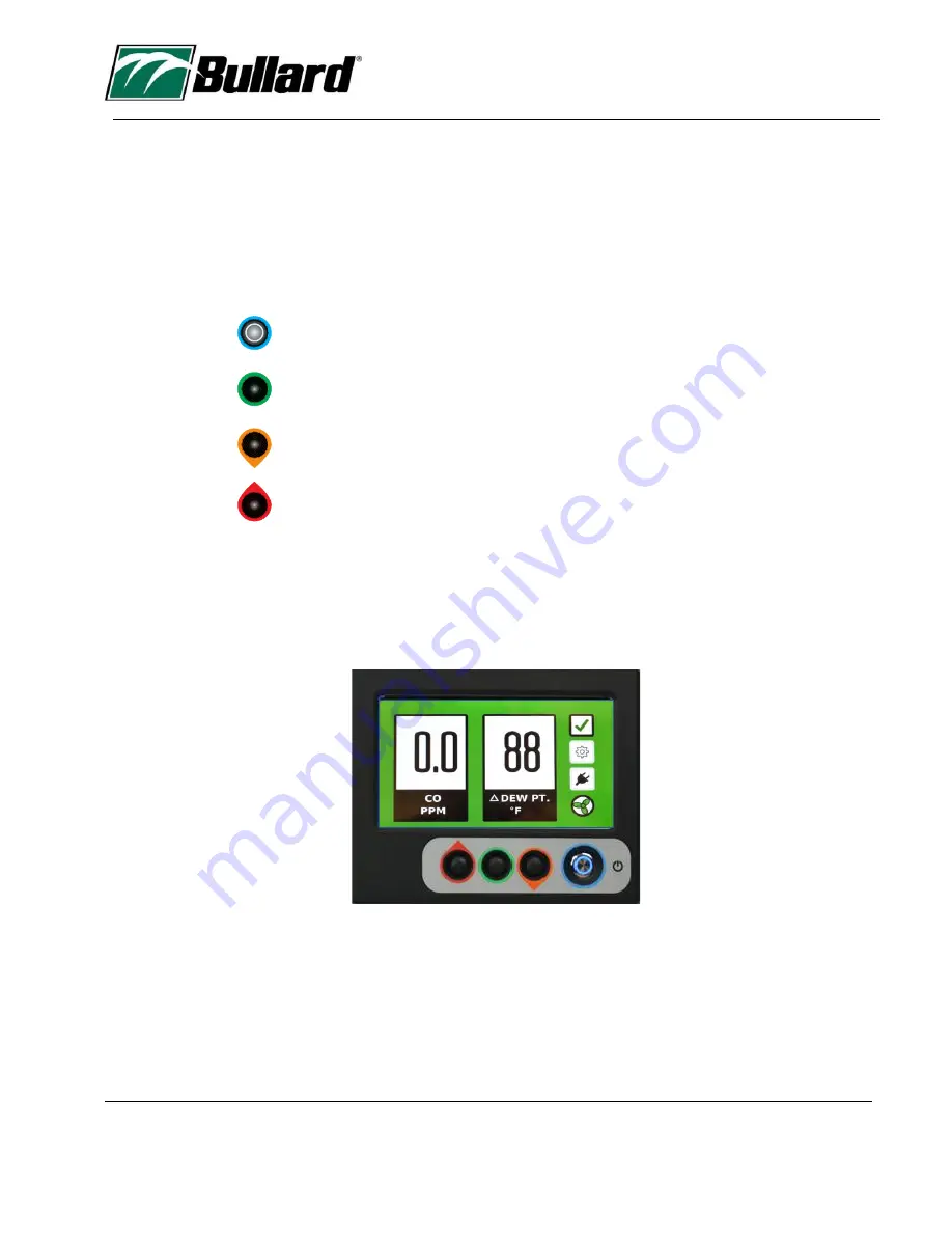
AirGuard uses a computer control menu interface which communicates using a Liquid Crystal Display (LCD).  Three 
buttons control this interface.  These buttons toggle the menu function selection, allow the adjustment of numeric 
values, and enter commands. 
 
This three-button interface is located directly under the LCD.  The buttons are color-coded, (left) red cursor up, 
(middle) green enter and (right) orange cursor down.  Additionally, the up-down buttons have a droplet point for 
direction to assist function direction. 
 

Power On/Off 
 
 
Green Enter Function 
 
 
Orange Cursor Down Selection 
 
 
Red Cursor Up Selection 

 
The main menu has three menu icons that allow access to menu functions and operational changes.  From the 
primary display, these icons are accessed by using the up/down buttons.  The active icon selection has a black 
border while the other icons will be grey.  The default position is located on the check icon. Toggling the buttons 
(orange button) down or (red button) up will change the icon selected position.  Upon selection of the desired 
function, press the middle green enter button to enter the function.  


Summary of Contents for Bullard AirGuard AGP

Page 1: ...AirGuardTM Operators Manual Revision 2 08 31 January 2022 ...

Page 2: ...ty 7 General Software Interface 8 Menu Function Interface Overview 9 Battery Operation 10 Compressor Pneumatic Connections 11 Start Up 14 Access Code 17 Bump Test 19 Sensor Menu 20 Calibration 23 Settings Menu 29 Maintenance Menu 31 Data Capture 32 Battery and Power Supply Operation 35 Case Exterior 36 ESD 36 Air Filtration Filters 36 General Filter and Sample Train Parts 37 AirGuard Parts 38 ...

Page 3: ...Affects personal safety If not followed may cause bodily injury or death Avertissement Affecte sécurité personnelle non suivi peut causer des blessures corporelles ou la mort General Safe Use Considerations AirGuard is an instrument designed for Grade D breathing air compliance It is important that the operator is trained by qualified personnel to ensure proper use The AirGuard is approved primari...

Page 4: ...impact recheck the calibration via a bump check and adjust if necessary Always have a trained and qualified person interpret the results to ensure safe operation Warning California Proposition 65 Warning Cancer and Reproductive Harm www P65Warning ca gov AirGuard Approvals Safety Requirements for Electrical Equipment for Measurement Control and Laboratory Use Part 1 General Requirements UL 61010 1...

Page 5: ...ature 5 F to 140 F or 15 C to 60 C Altitude Sea Level 1 200M Storage Ambient Humidity 10 to 95 RH non condensing Power Supply 100 260 VAC 50 60 Hz 10 Watts average to run unit and or charge battery Internal Battery 12V 7Ah rechargeable lead acid removable Battery Life 10 hours typical Local Alarm Signal Color display background and high intensity audible 90 dB horn Remote Alarm Signal Remote alarm...

Page 6: ...low Alarm Pt 5CFM 1 CFM Air Filter Train Filters 3 1 5 0 micron filter 2 0 01 micron filter and 3 carbon absorber filter Sensor response time 60 seconds Display Backlit 7 diagonal color display Keypad 3 button weatherproof w tactile feedback Data Logging 2 points per minute Data Storage Medium USB memory stick Calibration Span and Zero Recommended Monthly 60 Days Yellow Alert Warning 90 Days Red A...

Page 7: ...means and the desirable mode BULLARD shall not be liable for any loss or damage caused by the improper use or abuse of the product The purchaser indemnifies and saves harmless the company concerning any loss or damages that may arise through the application by the purchaser or others of this equipment This warranty is expressly given in place of all other warranties either expressed or implied inc...

Page 8: ...e up down buttons have a droplet point for direction to assist function direction Power On Off Green Enter Function Orange Cursor Down Selection Red Cursor Up Selection The main menu has three menu icons that allow access to menu functions and operational changes From the primary display these icons are accessed by using the up down buttons The active icon selection has a black border while the ot...

Page 9: ...mediate calibration or service and must not be used until the issue reported is resolved Should the status of the AirGuard change during operation the AirGuard will change the green check symbol along with the display background When the check symbol changes color the operator can press the enter button to display the AirGuard Status screen which will show the warning or fault encountered The alar...

Page 10: ... connector by screwing it together clockwise and then power the charger by connecting to main or wall power 100 to 240VAc power The battery can power the AirGuard for 16 hours of operation The AirGuard will indicate a low battery in two ways one through the main display battery icon turning red The other is a screen warning that will appear on the LCD If the charger is not connected the LCD will p...

Page 11: ...the maximum inlet pressure Attach the pneumatic hose from the compressor to the AirGuard To connect to the AirGuard inlet pull the outside ribbed ring away from the end of the compressor hose and push the connector into the receptacle port Release the ribbed connector to complete the connection Make sure the connection is secure Follow the same process in reverse to disconnect the hose Inlet Conne...

Page 12: ...12 www bullard com The following chart illustrates the CFM delivered at different inlet pressures ...

Page 13: ... to be used with AirGuard You need to know the pressure setting required for the correct flow Open the enclosure and adjust the delivery pressure by turning the regulator adjustment to the desired pressure to deliver required SCFM as per the NIOSH approved respirator being used Clockwise increases the pressure value Regulator Adjustment Knob ...

Page 14: ...arm up functions are finished the AirGuard status screen will display a report of 5 key metrics of operation 1 CO Alarm 2 Calibration Due 3 Flow Alarm 4 Differential Dew Point 5 Sensor Flow All parameters with a green check are satisfactory A red X will report an unsatisfactory operational status which will need to be corrected or cleared before use A yellow check mark will appear if there is a ca...

Page 15: ... to the exit function the main operation screen will appear Under this condition the main screen will display a dash in place of the carbon monoxide reading This is a safety measure to ensure the AirGuard is operating under the correct conditions of compressor flow Once compressor airflow is established the carbon monoxide value will appear ...

Page 16: ... the user must toggle down to the exit function and press enter Next the main screen will appear indicating the current CO concentration ppm and the differential dew point value in degrees Fahrenheit when connected to compressed air supply To change the unit to centigrade refer to page 22 Upon display of this screen the AirGuard is now in normal operational status ...

Page 17: ...e down or orange code button The gear icon outline will appear black and press enter green button The Access Code Screen will appear Enter the assigned access code the factory pre set is 2 7 0 Entering the correct code will take you to the Main Menu Settings screen if an incorrect code is entered the main alarm screen will appear Gear Icon ...

Page 18: ...and fan will turn green The AirGuard system status screen will display updated information clearing the flow alarm and sensor flow failures to green checks Once the gas flow is started it will take about 4 minutes for the LCD to report the measured gas concentration The range of acceptance on a 10 ppm CO standard is 9 ppm to 11 ppm If the gas concentration is outside of these values we recommend a...

Page 19: ...l the components to complete this test Part Number AGDCK Warning To perform a bump check the AirGuard must be disconnected from the compressor air supply Calibration cylinder must be connected to a pre determined or fixed flow regulator assembly with a male quick connect fitting and tubing attached to the regulator The calibration cylinder assembly tubing is then attached to the female calibration...

Page 20: ... have a bold border indicating it is active To adjust the values you must use the up and down buttons below the display You will move to the next value entry by pressing the enter button or going back to the previous menu 1 CO Carbon Monoxide displays the preset alarm values These values are user adjustable The maximum high level alarm setting is 10ppm A value setting higher than 10ppm cannot be e...

Page 21: ...ure is active only upon flow from the compressor and then loss of flow This is done to avoid audible alarm horn sounding if powered up prior to compressor connection To adjust the CFM alarm value toggle to alarm setpoint and adjust values between 2 and 9 CFM ...

Page 22: ...22 www bullard com 3 Dew Point setting is factory pre set to alarm as follows Yellow Alert Warning at 15 F Red Alarm at 10 F The AirGuard can report the delta dew point in either Fahrenheit or Celsius ...

Page 23: ...splay and using the keypad toggle the up or down arrow buttons to activate the gear icon Correct activation of the gear icon is observed by the grey outline becoming black Press the middle or green button on the keypad to enter the function menu Warning Make sure the compressor is disconnected from the AirGuard Toggle Up or Down to Calibration Menu select enter green button Gear Icon ...

Page 24: ... the Zero Gas 20 9 Oxygen cylinder Attach the regulator to the Zero Air cylinder The AirGuard will display a warning screen to make sure the compressor is disconnected Upon selecting NEXT the AirGuard will display a picture of the instrument and the gas connection location ...

Page 25: ...AirGuard will display a Zero in Progress display with a timer which counts down the time remaining in the zero function Upon completion the AirGuard will display a screen indicating the sensor voltage mV and also report sensor flow main flow and results A green check indicates a successful event Sensor voltage mv Zero gas reading can vary between 25 mV to 100mV Calibration Connection Charger Conne...

Page 26: ...sition Enter the Span Function Prepare the Span Gas 10 ppm Carbon Monoxide cylinder Attach the regulator to the Calibration Span cylinder Connect the regulator to the calibration port on the side of the AirGuard Open the gas regulator fully by turning the on off knob two turns counter clockwise The AirGuard will display a warning screen to make sure the compressor is disconnected ...

Page 27: ...e span function Upon completion the AirGuard will display a screen indicating the sensor voltage mV and report sensor flow main flow and results A green check indicates successful calibration event Sensor voltage mv Calibration Gas reading can vary between 200 mV to 350mV If a span is unsuccessful the AirGuard will display a fault screen The fault screen will appear if gas flow is not present or t...

Page 28: ...28 www bullard com Below is an example of the fail screen due to low flow and resulting sensor response ...

Page 29: ...enu The settings menu allows you to set the time and date as well as the horn function It is important to have the correct time and date so the datalog captures the correct information Note The clock will not update for daylight savings time ...

Page 30: ...rn signal either enables or disables the audio horn When the AirGuard is repowered these settings will resume enabled which is the default condition It is recommended that the horn be enabled to ensure alerts and safe operation ...

Page 31: ...TM 31 www bullard com Maintenance Menu AirGuard has several maintenance menus that record and store important information such as filter replacement installation date sensor installation date and total run time ...

Page 32: ...uses a removable USB which is located on the metal enclosure surrounding the microprocessor The USB can be read by either a MS Windows or Mac PC The full data log file is named as 2019 2 19 txt file and can be imported into a spreadsheet Excel ...

Page 33: ...AirGuardTM 33 www bullard com Upon opening in Excel the software will inquire about import format using text import wizard The arrow indicated the correct radio icon selection ...

Page 34: ...34 www bullard com After parameter selection the log will open in Excel for further data and plotting analysis ...

Page 35: ...o operate AirGuard it will also charge the battery To recharge the battery the connector must be fully inserted and then screwed into the charge port until tight AirGuard Battery Malfunction If the AirGuard will not power up it is due to a discharged battery If this occurs connect the battery charger to the AirGuard The charger LED should immediately turn red indicating charging If the LED remains...

Page 36: ...ins electrostatically sensitive components Do not open or repair the device without using appropriate electrostatic discharge ESD protection The warranty does not cover damage caused by electrostatic discharges Air Filtration Filters Warning Replace all three filter elements when the coalescing filter indicator is red Filter Indicator Green Ok Red Bad ...

Page 37: ...cing Position C Charcoal Adsorption Filter The filter bowls are attached to the air flow sample train using a 1 3 or 120 rotation twist To remove the filter from the air train push the filter bowl up and in towards the sample train gas flow and twist counter clockwise and then pull down That will expose the filter component The filter can be removed by rotating it counter clockwise until released ...

Page 38: ...0CFM Replacement Filter Kit AGD30FK 100CFM Replacement Filter Kit AGD50 and 100FK Battery Assembly AGDBAT CO Sensor AGDCOS Regulator Assy CGA600 AGDREGTB AirGuard Calibration Kit AGDCK LCD Clear Overlay Pk 5 AGDLC AirGuard 15 CFM AGD15HA AirGuard 30 CFM AGD30HA AirGuard 50 CFM AGD50HA AirGuard 100 CFM AGD100HA ...

Page 39: ...AirGuardTM 39 www bullard com Notes ...

Reviews: