background image


IMPORTANT!

  READ AND FOLLOW 

ALL

 INSTALLATION AND MAINTENANCE INSTRUCTIONS, INCLUDING 

CLEANING THE UNIT AS SPECIFIED, AND REPLACING GASKETS ANNUALLY, AND PARTS AS NEEDED. 

ENGLAND’S STOVE WORKS IS NOT RESPONSIBLE FOR ANY DAMAGE OR INJURY INCURRED DUE TO NEGLECT, OR 

DUE TO UNSAFE INSTALLATION OR USAGE OF THIS PRODUCT. CALL TECHNICAL SUPPORT WITH ANY QUESTIONS. 

13

OPERATING INSTRUCTIONS 


CAUTION: DO NOT OPERATE WITH THE DOOR OPEN. 


If door is left open (approximately) two minutes, unit will stop feeding and fire will go out. 

Do not burn trash (paper bags, etc.) in this unit. 


This stove has an induced draft system and is designed to operate continuously, as frequent 

shutdown is not required.  The digital control board operates the unit with a time delay-relay system; 
this system controls the top auger feed rate by operating for a predetermined number of seconds 
while the bottom auger runs constantly.  The setting of the 

“Heat Range”

 touch pad will control the 

heat output and the amount of pellets the unit will burn (see “Control Board” section and  

Illustration 3

).  Note: This stove is using solid fuel and will not restart automatically.     

NOTE: 

Blower Speed will automatically be adjusted to the desired Heat Range that you select.


Horizontal Feed System 

This unit has a top and a bottom auger that are separated by four inches (4”); a 1-RPM motor 

drives each auger. The top auger intermittently drops pellets to the bottom auger tube, and the 
bottom auger pushes the pellets forward to the burn pot. This helps prevent build-up of fuel in the 
bottom auger tube. As pellets enter the burn pot the combustion air is drawn across the fuel. 


START- UP PROCEDURE 


Caution - Never use gasoline, lantern fuel, charcoal lighter fluid, diesel fuel, or any other 

flammable liquid to start the fire.  


1. 

Be sure the hopper is clean and free from foreign materials.  Be sure there is current at your 
outlet (we do recommend a surge protector with our unit). 


2. 

Before

 your first fire 

dry run your unit (with no pellets in the hopper)

 for 20 minutes.  Press 

the “ON” button to begin the dry run.  After the 20 minute dry run, the control board will return 
to “OFF.”  An error code will appear in the Heat Range and the Blower Speed windows as  

E-2

,” which means the unit failed to start normally. After this code is received and you are sure 

the unit is working properly, fill the hopper with wood pellets.  Do not allow any part of the bag 
or any foreign material in the hopper, as this may jam the augers.  Ensure that all pellet matter 
is cleared from the hopper lid gasket, make sure the hopper lid latches and the door of the unit 
are securely closed and press the “ON” button; this will clear the error code and restart your 
unit. 


Automatic Start-Up 

When the “ON” button is pressed from a cold start, the unit is in “Start-Up” (after 3 seconds, there 
will be an “S U” in the Heat Range and Blower Speed windows to verify this).  While in this mode, 
the unit has a preset heat range and will remain in this mode for 20 minutes to prevent the unit 
from over-firing. During this start-up period you can set the Control Board at the setting you 
desire; after the start-up is complete, the unit will operate at the user setting.   


Manually Starting Your Unit 

In the event the Auto-Start does not initiate, you may manually start your unit.  To manually start 
your unit, first clean any pellets out of the burn pot (to prevent over-feeding).  Place a handful of 
new pellets in the burn pot, then spread a small amount of pellet fire starter over the pellets and 
ignite them.  After the pellets ignite, close the door to your unit and press the “ON” button (if the 
door is closed before the pellets fully ignite, the Exhaust Blower could put out the fire).  
Recommended fire starter materials:  Wax-impregnated wood chips, cardboard cubes or 
firestarter chips designed for pellet stoves.  Follow any manufacturer’s directions for these 
products, and NEVER place any firestarter on any hot surface or hot coals.  Never use gasoline, 
lantern fuel, kerosene, charcoal lighter fluid, diesel fuel or any other flammable liquid to start the 

Summary of Contents for 25-PDVC

Page 1: ... Manufactured By England s Stove Works Inc PO Box 206 Monroe VA 24574 Rev 6 2020 Pellet Stove MODELS 25 PDVC 25 PDVCH 55 SHP10 55 SHP10L 55 TRP10 SAVE THESE INSTRUCTIONS www heatredefined com Parts 800 516 3636 Support 800 245 6489 ...

Page 2: ...des 14 Shut Down Procedure 14 Daily Operation 15 Refueling 15 Power Outage 15 Fuel Outage 15 Combustion Blower Failure 15 Ash Removal Maintenance Daily 16 Semi Weekly 16 Monthly 17 Annual 17 Rear Panel Removal 18 Auger Motors 18 Auger Bearings Shafts 18 Convection Blower 18 Combustion Blower 18 Vacuum Switch 19 Vacuum Switch Port 19 Hopper Lid Switch 20 Gaskets 20 Finish 20 Glass 20 Control Board ...

Page 3: ...ON INSTRUCTIONS CONTACT YOUR LOCAL BUILDING OR FIRE OFFICIALS FOR RESTRICTIONS AND INSTALLATION INSPECTION REQUIREMENTS INCLUDING PERMITS IN YOUR AREA Questions Need Parts or Options www HeatRedefined com England s Stove Works highly recommends the use of smoke detectors and Carbon Monoxide detectors with any hearth product including this unit Follow all manufacturer s instructions when using smok...

Page 4: ...el U S Test Standard US EPA 40 CFR Part 60 Subpart 60 536 Particulate Emissions 1 430 grams hr CO Emissions 0 0 grams min Efficiency 68 4 HHV BTU rating 26 179 BTU hr Tested To UL 1482 00 ASTM E 1509 ULC ORD C1482 M1990 ULC S627 00 Notes for this unit Product may vary slightly from diagram Clearances are the minimum for this unit and may need to be increased in the rear to have proper vent clearan...

Page 5: ...cal Support department at 800 245 6489 if you need any help with your unit We are nearly always able to help walk you through any repairs problems or questions you may have PLEASE NOTE While information obtained on our web site and through our 800 number is always free of charge there will be a service charge incurred with any on site repairs or maintenance that we may arrange Wishing you years of...

Page 6: ...tral Furnace you must place your stove at least 20 feet 20 from the Cold Air Return We recommend you open an outside window slightly and never close the door that leads from this room to the rest of your home IN THE EVENT OF SMOKE BACK 1 If you see smoke coming out of your unit into the room due to a power failure DO NOT OPEN THE HOPPER OR DOOR TO YOUR UNIT Remain calm DO NOT UNPLUG UNIT Open the ...

Page 7: ...d twist lock pellet pipe be sure to use U L approved Pellet Vent pipe and fasten each joint of the pipe with at least three screws ULC approved if Canada Outside combustion air is mandatory for these units to work properly Make this connection using a 1 7 8 I D metal pipe steel aluminum or copper and coupler Be sure to secure the pipe to the unit with a clamp or aluminum tape The outside end shoul...

Page 8: ...irections for these products and NEVER place any firestarter on any hot surface or hot coals Never apply any firestarter products of any kind to a hot surface or hot coals 18 Basement Installation We recommend basement installation be performed only by a professional installer For basement installations a 3 three inch pipe and coupler must be used for Outside Combustion Air and a minimum clearance...

Page 9: ...o a flue system serving another heating appliance Through the Wall To vent the unit through the wall connect the pipe adapter to the exhaust motor adapter If the exhaust adapter is at least eighteen inches 18 above ground level a straight section of pellet pipe can be used to initially pass through the wall see Illustration 1 Your dealer or our factory should be able to provide you with a kit that...

Page 10: ...chimney professional can confirm this upon inspection Outside Air Outside Combustion Air Intake Outside air is mandatory for this unit to operate properly This unit has been designed and tested with this connection because so many homes are airtight and there is not adequate combustion air available inside the dwelling The air intake pipe is located on the bottom side of the burn pot from the rear...

Page 11: ...ed to paneling wallpaper or drywall The pellet vent pipe usually requires the standard three inches 3 of clearance or as recommended by the manufacturer Normally additional wall protection is not required with this type unit 1 If 3 flue pipe exceeds 15 in length increase to 4 flue pipe for remaining flue connections 2 Total flue length should not exceed 35 3 Horizontal run not to exceed 4 4 Floor ...

Page 12: ...THROUGH THE ROOF SURFACE Notes on termination of Pellet Vent Pipe from NFPA 211 2006 ed Section 10 4 Termination 10 4 5 See also FLUE SYSTEM section of manual AND additional notes above Not less than three 3 feet above any forced air inlet located within ten 10 feet Not less than four 4 feet below four 4 feet horizontally from or one 1 foot above any door window or gravity air inlet into any build...

Page 13: ... Before your first fire dry run your unit with no pellets in the hopper for 20 minutes Press the ON button to begin the dry run After the 20 minute dry run the control board will return to OFF An error code will appear in the Heat Range and the Blower Speed windows as E 2 which means the unit failed to start normally After this code is received and you are sure the unit is working properly fill th...

Page 14: ...is 13 minutes Press the ON button only once on start up Pressing the ON button a second time during the start up cycle will cause the start up cycle to begin again IMPORTANT If the unit fails to start properly or does not properly complete the Shut Down procedure open the closest outside door and a window to eliminate the home s natural draft BEFORE opening the stove s door or hopper lid This will...

Page 15: ...OT open the hopper lid or the door to the unit during power outage Open the closest outside door and a window to eliminate the home s natural draft Wait for power to be restored and then press the ON button to re start the unit if necessary We highly recommend the use of a surge protector with your unit as power surges and failures can affect the operation of any electrical appliance We do not rec...

Page 16: ...pection Remove and clean the burn pot wear plate refer to the exploded diagram in the rear of this manual Illustration 6 and the close up diagram shown here and remove any ash build up in the area below the wear plate Also be sure there are no ashes or obstructions in the tube under the wear plate Check for any build up in the front of the burn area Clean out all air holes if necessary a 1 8 drill...

Page 17: ...is carbon residue from the feed tube is essential for proper operation of the feed auger which is designed to float freely in the feed tube allowing smooth fuel flow a lesser possibility of a jam and a quieter unit Annual Cleaning The stove and the flue system should be given a complete cleaning at the end of the heating season Remove the burn pot assembly clean it thoroughly and re install it ref...

Page 18: ...ting the unit Auger Bearings and Auger Shafts The auger bearings Part PU UCF204 12 are a sealed unit and do not require lubrication To replace the Top Auger all the fuel must be removed from the hopper as well as from the Top Auger assembly Once this is done the four bolts that hold in the bearing can be removed followed by the complete auger assembly Loosen the two 2 set screws with a 1 8 Allen w...

Page 19: ...p feed auger or shut the unit off if the unit turns off an E 1 Code error code will appear in the Heat Range and Blower Speed windows of the Control Board Situations which could cause this include power failure Combustion Blower failure improper flue installation a blocked flue from rodents nests etc or dirty burning from burning improper fuel see Important Information at the beginning of the manu...

Page 20: ...ding the new adhesive you may have to scrape the old cement from the door channel Once the cement and gasket have been added the door should be closed and latched for twenty four hours to allow the cement to harden If you are replacing the window gasket Part AC GGK the new gasket will already have adhesive on one side Remove the paper on the adhesive side and place the gasket around the outside ed...

Page 21: ...nd should not require any changes See Operating Instructions and Daily Operation section of the manual for instructions on other Control Board settings Recommended Heat Ranges Low Burn Heat Range setting 1 Room Air Blower setting 1 Medium Low Heat Range setting 2 3 Room Air Blower setting Medium High Heat Range setting 5 8 Room Air Blower setting High Burn Heat Range setting 9 Room Air Blower sett...

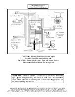
Page 22: ... USAGE OF THIS PRODUCT CALL TECHNICAL SUPPORT WITH ANY QUESTIONS 22 CAUTION Moving Parts May Cause Injury Do NOT Operate with Panel s Off DANGER Parts May Be Hot Risk of Electric Shock Disconnect Power Before Servicing Unit Illustration 4 PU CB19 Control Board Wiring Diagram IMPORTANT SAFETY NOTE If the unit or chimney connector pipe glows red or white the stove is over fired This condition could ...

Page 23: ...ols will be needed two inch wrenches or a inch wrench and a inch socket In order to adjust the latch first with the unit unplugged and cooled down open the hopper lid and then lock the latch in its closed position Then take the inch wrench and loosen the nut closest to the latch This nut is then adjusted closer to the lid itself to tighten the latch After adjusting this nut to the desired location...

Page 24: ...ng the thermostat Refer to the section on Start up Procedure for information on cold starts AC 103 AC 103BN Lip Trim There is one piece of J Channel trim in this kit that snaps onto the ash apron lip of the stove Match the channel with the correct edge of the ash apron then remove the protective covering from the trim and force the piece onto the edge Although it should stay in place stove cement ...

Page 25: ...agram PU UCF204 12 Auger Bearing 16 on diagram PU 2X570 Locking Collar 17 on diagram PU CB19 Digital Control Board 12 on diagram PU CB04 if stove Serial Number is below 150 000 CU VS Second Vacuum Switch See wiring diagram pg 19 PU CBMG Combustion Blower and Motor Gasket 10 on diagram PU BPG Burn Pot Gasket 6 on diagram PU ABGN Auger Bearing Gasket 15 on diagram PU HLG Hopper Lid Gasket 22 on diag...

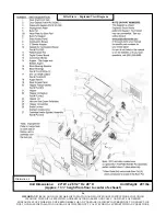
Page 26: ...S NEEDED ENGLAND S STOVE WORKS IS NOT RESPONSIBLE FOR ANY DAMAGE OR INJURY INCURRED DUE TO NEGLECT OR DUE TO UNSAFE INSTALLATION OR USAGE OF THIS PRODUCT CALL TECHNICAL SUPPORT WITH ANY QUESTIONS 26 Pellet Stove Exploded View Diagram Illustration 6 Unit Dimensions 24 W x 28 1 2 H x 28 D Unit Weight 291 lbs Approx 13 height from floor to center of exhaust ...

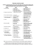
Page 27: ...um sensor 3 Replace vacuum sensor 5 Lazy fire 1 Control board settings 1 Review board settings 2 Bad exhaust blower 2 Replace blower 3 Excessive pellet moisture 3 Keep pellets inside 4 Excessive ash 4 Remove baffles Clean unit 5 Low quality pellets 5 Use premium pellets 6 Blown fuse 6 AMP 1 Power surge 1 Replace fuse use surge protector 2 Exposed wire 2 Check for exposed or frayed wire and loose c...

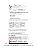
Page 28: ...R ANY DAMAGE OR INJURY INCURRED DUE TO NEGLECT OR DUE TO UNSAFE INSTALLATION OR USAGE OF THIS PRODUCT CALL TECHNICAL SUPPORT WITH ANY QUESTIONS 28 You may write your unit s Manufacture Date and Serial Number in the blank spaces on this sample tag for future reference This sample tag also shows the safety info such as UL ULC testing standard etc for your local officials or anyone else who may need ...

Page 29: ...om the date of purchase Conditions and Exclusions Damage from over firing will void your warranty This warranty does not apply if damage occurs because of an accident improper handling improper installation improper operation abuse or unauthorized repair made or attempted to be made The manufacturer is not liable for indirect incidental or consequential damages in connection with the product inclu...

Page 30: ...UDING CLEANING THE UNIT AS SPECIFIED AND REPLACING GASKETS ANNUALLY AND PARTS AS NEEDED ENGLAND S STOVE WORKS IS NOT RESPONSIBLE FOR ANY DAMAGE OR INJURY INCURRED DUE TO NEGLECT OR DUE TO UNSAFE INSTALLATION OR USAGE OF THIS PRODUCT CALL TECHNICAL SUPPORT WITH ANY QUESTIONS 30 ...

Page 31: ...______ Zip _________________ UNIT INFORMATION Please be sure to refer to sticker on back of manual or box to complete this section Model Number _______________________ Purchase Date ____________________ Purchase Price _______________________ Serial Number _______________________ Mfg Date ________________________ How did you first hear about our product please check one ___ Word of Mouth ___ Burn T...

Page 32: ...UDING CLEANING THE UNIT AS SPECIFIED AND REPLACING GASKETS ANNUALLY AND PARTS AS NEEDED ENGLAND S STOVE WORKS IS NOT RESPONSIBLE FOR ANY DAMAGE OR INJURY INCURRED DUE TO NEGLECT OR DUE TO UNSAFE INSTALLATION OR USAGE OF THIS PRODUCT CALL TECHNICAL SUPPORT WITH ANY QUESTIONS 32 ...

Page 33: ...mbustion air is MANDATORY for proper safe operation and to achieve optimal emissions performance Observe the vent termination clearances specified in your owner s manual and contact our Technical Support if you have any questions Phone 800 245 6489 or email service englanderstoves com Be certain that all aspects of the venting system are installed to the venting manufacturer s instructions particu...

Page 34: ...f a mechanical draft system other than direct vent appliances sealed combustion system appliances shall be located in accordance with the following a Not less than 3 ft 91 m above any forced air inlet located within 10 ft 3 0m b Not less than 4 ft 1 2 m below 4 ft 1 2 m horizontally from or 1 ft 305 mm above any door window or gravity air inlet into any building c Not less than 2 ft 0 61 m from an...

Page 35: ...uld be avoided Due to frictional resistance in pipe any excessive outside air piping can result in poor stove performance A screen or other protection device must be fitted over the outside air termination point to prevent rain debris and nuisance animals from entering the piping system Increase the outside air pipe size to 3 0 in diameter pipe if the outside air connection is more than 6 ft in le...

Page 36: ...fire This pellet burning room heater is equipped with a specially designed burn pot which comes preinstalled from the factory This burn pot elevates the burning pellets and delivers air at the precisely required locations Pellets must only be burned in the factory burn pot no modifications should be made to this burn pot and no additional grates or other fire elevators should be used WHAT FUELS NO...

Page 37: ...n should turn red and the board should display S d shortly after pressing the button This initiates the shut down sequence and the stove will remain in shut down mode until it has cooled down To increase the heat output of the stove press the Up heat range button The number in the heat range display window will increase signifying that the control board is now adjusting the heat output to your des...

Page 38: ...ion It is against federal regulations to operate this wood heater in a manner inconsistent with operating instructions in this manual Smoke Detectors England s Stove Works Inc highly recommends the use of smoke detectors in every room of the house However locating a smoke detector directly above this unit can result in nuisance alarms Compliance This non catalytic wood heater meets the 2015 U S En...

Page 39: ......

Page 40: ... RESTRICTIONS ET LES EXIGENCES D INSPECTION DES INSTALLATIONS Y COMPRIS L OBTENTION DE PERMIS PROPRES À VOTRE RÉGION Fabriqué par England s Stove Works Inc PO Box 206 Monroe VA 24574 États Unis 6 2020 CONSERVEZ CES INSTRUCTIONS AFIN D ASSURER LE BON FONCTIONNEMENT DU POELE A BOIS VOUS DEVEZ L INSPECTER ET LE REPARER PERIODIQUEMENT CONSULTEZ LE GUIDE D UTILISATION POUR OBTENIR DE PLUS AMPLES RENSEI...

Page 41: ...E REDÉMARRER VOTRE APPAREIL 6 INFORMATION IMPORTANTE 7 PRÉPARATION DE L APPAREIL 8 Installation SYSTÈME DE CONDUIT DE FUMÉE 9 INSTALLATION CONT 10 DÉGAGEMENTS DES TERMINAISONS DES ÉVENTS 11 DIRECTIVES D UTILISATION 12 E CODES 14 PROCÉDURE D ARRÊT 14 Utilisation quotidienne UTILISATION QUOTIDIENNE 15 NETTOYAGE NETTOYAGE ET ÉLIMINATION DES CENDRES 16 NETTOYAGE MENSUEL ANNUEL 17 ENTRETIEN 18 COMMUTAT...

Page 42: ...ALLATION COMMUNIQUER AVEC LE SERVICE LOCAL DE LA CONSTRUCTION OU LE SERVICE D INCENDIE RELATIVEMENT AUX RESTRICTIONS ET AUX EXIGENCES D INSPECTION DE L INSTALLATION Y COMPRIS LES PERMIS DANS VOTRE QUARTIER England s Stove Works recommande l utilisation de détecteurs de fumée et de monoxyde de carbone avec tout produit avec foyer y compris cet appareil Suivre les directives du fabricant relativemen...

Page 43: ...ai des États Unis règlement 40 CFR de l EPA des États Unis article 60 alinéa 60 536 Émissions de particules 1 430 g h Émissions de CO2 0 00 g min Efficacité 68 4 PCS Classement BTU 26 179 BTU h Testé selon les normes UL 1482 00 ASTM E 1509 ULC ORD C1482 M1990 et ULC S627 00 Remarques pour cet appareil Le produit peut différer légèrement de l illustration Les distances indiquées pour cet appareil r...

Page 44: ...et de votre appareil veuillez consulter la vaste section d aide de notre site Web ou appeler notre service de soutien technique au 1 800 245 6489 Nous sommes presque toujours en mesure de vous guider en cas de réparation à effectuer ou de problème ou encore de répondre à vos questions REMARQUE Les renseignements obtenus sur notre site Web ou en composant notre numéro sans frais sont gratuits en to...

Page 45: ...l en particulier s il est trop près de l appareil de chauffage central de la maison Si vous installez votre poêle dans la même pièce que la reprise d air froid du chauffage central vous devez le placer à plus de 6 m 20 pi de la reprise d air froid Nous vous recommandons de laisser une fenêtre entrouverte et de ne jamais fermer la porte entre cette pièce et le reste de la maison DANS LE CAS D UN RE...

Page 46: ...on de l appareil De plus si vous n utilisez pas un tuyau pour granules à verrouillage par rotation homologué U L veiller à utiliser un tuyau pour granules homologué U L et fixer chaque raccord du tuyau avec au moins trois vis ULC si le Canada De l air comburant extérieur est obligatoire pour que ces appareils fonctionnent correctement Faire cette connexion à l aide d un tuyau métallique d 1 7 8 po...

Page 47: ...on chauds Ne jamais appliquer de produits allume feu sur une surface chaude ou des charbon chauds 18 Installation au sous sol Nous recommandons qu une installation au sous sol soit effectuée uniquement par un installateur professionnel Pour les installations au sous sol il faut utiliser un tuyau de 3 po 75 mm et un raccord pour l air comburant extérieur et il faut conserver un espacement minimal d...

Page 48: ... dessus du niveau de la mer l évacuation doit être ventilée par du conduit pour poêles à granules de 4 po 100 mm Kit AC 3100 AC 33100 si le Canada Ne pas installer de registre de tirage clapet de quelque sorte dans ce système et ne pas raccorder l appareil à un système de conduit de fumée qui dessert un autre appareil de chauffage À travers le mur Pour l évacuation de l appareil à travers le mur r...

Page 49: ...aut tenir compte de la section du carneau Dans le cas d une cheminée avec un conduit plus grand que 6 po rond 28 27 po2 182 cm2 il pourrait être nécessaire de refaire un revêtement intérieur à l aide d un tuyau approuvé pour poêle à granules Veiller aussi à ce que la cheminée respecte les normes minimales de la NFPA 211 un fumiste peut le confirmer après inspection Air extérieur Prise d air combur...

Page 50: ...x lambris papier peint ou gyproc Le tuyau de conduit pour poêle à granules nécessite un espacement standard de 75 mm 3 po ou selon la recommandation du fabricant Normalement aucune autre protection murale n est nécessaire avec cet appareil 1 Si le tuyau de conduit de fumée 3 po 75 mm dépasse 4 57 m 15 pi augmenter le diamètre à 4 po 100 mm pour les autres raccordements du conduit 2 La longueur tot...

Page 51: ...S I VENTS INSTALLE AVEC ASPIRATEURS MÉCANIQUES SE TERMINE AU MOINS 12 PO 305 MM AU DESSUS DU PLUS HAUT POINT OU ILS TRAVERSENT LA SURFACE DU TOIT Notes sur les extrémités de tuyau de conduit pour poêle à granules Consulter aussi le chapitre SYSTÈME DE CONDUIT DE FUMÉE 1 À plus de 0 91 m 3 pi au dessus d une entrée d air forcé situé dans les 3 m 10 pi 2 À plus d 1 20 m 4 pi sous ou horizontalement ...

Page 52: ...2 Avant votre premier feu faire fonctionner votre appareil à sec sans granules dans la trémie pendant 20 minutes Appuyer sur le bouton ON pour commencer la marche à vide Après 20 minutes de marche à vide le tableau de commande reviendra à OFF Un code d erreur apparaîtra dans les fenêtres de la plage de température et de la vitesse du ventilateur comme E 2 ce qui signifie que l appareil n a pas dém...

Page 53: ...r le bouton ON une fois seulement au démarrage Appuyer sur le bouton ON une deuxième fois pendant le cycle de démarrage fera recommencer celui ci IMPORTANT Si l appareil ne démarre pas normalement ou n effectue pas correctement la procédure d arrêt ouvrir la porte extérieure la plus proche et une fenêtre pour éliminer le tirage naturel de la maison AVANT d ouvrir la porte et le couvercle de la tré...

Page 54: ...le couvercle de la trémie ou la porte de l appareil pendant une panne de courant Ouvrir la porte extérieure la plus proche et une fenêtre pour éliminer le tirage naturel de la maison Attendre le retour du courant et appuyer en suite sur le bouton ON pour redémarrer l appareil au besoin Nous recommandons fortement un parasurtenseur pour votre poêle car les surtensions et les pannes peuvent affecter...

Page 55: ...etirer et nettoyer la plaque d usure de la chambre de combustion Consulter la vue éclatée au dos de ce manuel Illustration 6 et la vue en gros plan montré ici retirer toute accumulation de cendres dans l aire située sous la plaque d usure Veiller également à ce qu il n y ait pas de cendres ou d obstructions dans le tube sous la plaque d usure Vérifier la présence d une accumulation à l avant de l ...

Page 56: ...idu que le grattage a laissé Nettoyer ce résidu de carbone du tube d alimentation est nécessaire à un bon fonctionnement de la vis d alimentation conçue pour flotter librement dans le tube et permettant un flux régulier de combustible moins de possibilité de bourrage et que l appareil soit plus silencieux Nettoyage annuel Il faut faire un nettoyage complet du poêle et du système de conduit de fumé...

Page 57: ...le doit toujours être placé afin de reposer sur cette étagère avant de démarrer l appareil Coussinets et arbres de vis sans fin Les coussinets de vis sans fin Pièce PU UCF204 12 sont des unités scellées et n ont pas besoin d être lubrifiés Pour remplacer la vis supérieure il faut retirer tout le combustible de la trémie ainsi que de la vis Par la suite les quatre boulons qui retiennent le coussine...

Page 58: ...rrêtera la vis sans fin supérieure alimentation ou arrêtera l appareil dans le cas de l arrêt de l appareil un code E 1 code d erreur apparaîtra dans les fenêtres du degré de chaleur et de la vitesse du ventilateur du tableau de commande Les situations pouvant causer ceci comprennent la panne de courant celle du ventilateur de combustion une mauvaise installation du conduit de fumée un conduit obs...

Page 59: ...9 05 mm autour de la porte qui doit être remplacé annuellement Pour remplacer le joint de la porte Pièce AC DGKC il faut retirer complètement le vieux joint avant de mettre la nouvelle colle vous pourriez devoir gratter le vieux ciment de la gorge de la porte Une fois le ciment et le joint posé il faut fermé la porte et la garder verrouiller pendant vingt quatre heures pour laisser le ciment durci...

Page 60: ...t ne demandent pas de changements Consulter le chapitre Instructions d utilisation et Utilisation quotidienne du manuel pour des directives sur d autres réglages du tableau de commande Degrés de chaleur recommandés Combustion basse Réglage du degré de chaleur 1 Réglage du ventilateur d air ambiant Moyen Bas Réglage du degré de chaleur 2 3Réglage du ventilateur d air ambiant Moyen haut Réglage du d...

Page 61: ...raient être chaudes Risques de choc électrique Déconnecter l alimentation électrique avant de faire l entretien de l appareil IMPORTANTE NOTE DE SÉCURITÉ Si l appareil ou le tuyau de cheminée rougeoie ou blanchit le poêle surchauffe Cet état peut causer un incendie ou un feu de cheminée Ne pas trop chauffer l appareil ou il pourrait résulter une surchauffe Illustration 4 PU CB19 Schéma du tableau ...

Page 62: ...ts périodiquement et ajuster au besoin Pour ajuster les loquets du couvercle vous aurez besoin des outils suivants deux clés d pouce ou une clé d pouce et une douille d pouce Afin d ajuster le loquet ouvrir d abord le couvercle de la trémie puis verrouiller le loquet en position fermée Prendre alors la clé d pouce et desserrer l écrou le plus proche du loquet Ajuster ensuite l écrou plus près du c...

Page 63: ... la vitesse du ventilateur à 9 sur le tableau de commande Consulter le chapitre Procédure de démarrage pour de l information sur les démarrage à froid Moulure de rebord AC 103 AC 103BN Il y a un dans ce kit une garniture profilé en J qui s enclenche sur la lèvre du tablier à cendres Ajuster la gorge en J avec le bon bord du tablier à cendres puis retirer le protection de la garniture et forcer cel...

Page 64: ...modèles plus anciens commander PU 103 50 25 sur le schéma PU UCF204 12 Coussinet de vis sans fin 16 sur le schéma PU 2X570 Bague de blocage 17 sur le schéma PU CB19 Tableau de commande Voir schéma du tableau de commande PU CB04 si le numéro de série du poêle est inférieur à 150 000 CU VS Second interrupteur d aspiration Voir schéma du tableau de commande PU CBMG Joint d étanchéité du ventilateur d...

Page 65: ...e Works n est pas responsable des dommages ni des blessures quels qu ils soient subis en raison de négligence ou à cause d une installation ou utilisation dangereuse de ce produit Pour toute question communiquez avec le service de soutien technique Poêle à granules de bois Vue éclatée Illustration 6 Dimensions de votre appareil à granules L 61 cm x H 72 4 cm x P 71 1 cm 24 po x 28 5 po x 28 po 132...

Page 66: ...ur d aspiration 5 Feu paresseux 1 Réglages du tableau de commande 1 Revoir les réglages du tableau 2 Ventilateur évacuation défectueux 2 Remplacer le ventilateur 3 Humidité excessive des granules 3 Entreposer les granules à l intérieur 4 Trop de cendres 4 Enlever les déflecteurs nettoyer l appareil 5 Granules de qualité inférieure 5 Utiliser des granules de qualité supérieure 6 Fusible brûle 6 A 1...

Page 67: ...ils soient subis en raison de négligence ou à cause d une installation ou utilisation dangereuse de ce produit Pour toute question communiquez avec le service de soutien technique Vous pouvez inscrire la date de fabrication et le numéro de série de votre appareil dans les espaces prévus à cet effet sur cette étiquette pour référence ultérieure Cette étiquette comprend également des renseignements ...

Page 68: ...l achat Conditions et exclusions Les dommages dus à la surchauffe annuleront la garantie Cette garantie ne s applique pas en cas de dommage causé par un accident une mauvaise manipulation une installation défectueuse une mauvaise utilisation un abus ou une réparation non autorisée faite ou tentée d être faite Le fabricant n est pas responsable des dommages indirects accessoires ou immatériels en r...

Page 69: ...les directives et celles portant sur le remplacement des joints annuellement et des pièces au besoin England s Stove Works n est pas responsable des dommages ni des blessures quels qu ils soient subis en raison de négligence ou à cause d une installation ou utilisation dangereuse de ce produit Pour toute question communiquez avec le service de soutien technique ...

Page 70: ..._________________ Province__________ Zip _________________ INFORMATION SUR L APPAREIL Veuillez vous assurer de consulter l étiquette au dos de ce manuel ou sur la boîte pour remplir cette section Numéro de modèle _______________________Date d achat ____________________ Prix d achat _______________________ Numéro de série _______________________ Date de fabrication ________________________ Comment ...

Page 71: ...les directives et celles portant sur le remplacement des joints annuellement et des pièces au besoin England s Stove Works n est pas responsable des dommages ni des blessures quels qu ils soient subis en raison de négligence ou à cause d une installation ou utilisation dangereuse de ce produit Pour toute question communiquez avec le service de soutien technique ...

Page 72: ...illez également noter que le raccord d air extérieur air de combustion est OBLIGATOIRE pour faire fonctionner le poêle de manière appropriée et sécuritaire et pour réduire au minimum les émissions Comme indiqué dans le guide d utilisation les terminaisons des évents doivent être dégagées communiquez avec le service de soutien technique si vous avez des questions Composez le 1 800 245 6489 ou envoy...

Page 73: ...es autres ouvertures d une résidence o NFPA 211 version 2006 Section 10 4 Terminaison 10 4 5 1 L extrémité de sortie des systèmes mécaniques de tirage autres que les dispositifs de ventilation directe dispositifs pour des appareils à combustion étanche doit être située conformément aux indications suivantes a À au moins 0 91 m 3 pi au dessus de toute prise d air par ventilation forcée située dans ...

Page 74: ...rande longueur de tuyau et d y former un nombre excessif de coudes En raison de la résistance au frottement dans le tuyau le rendement du poêle sera réduit si le tuyau de raccordement à l air extérieur est trop long Une grille ou un autre dispositif de protection doit être placé à l extrémité du tuyau de raccordement à l air extérieur afin d éviter que la pluie des débris ou des animaux nuisibles ...

Page 75: ...e déclarer Ce poêle à granules est muni d un pot de combustion spécialement conçu qui a été installé en usine Ce pot de combustion élève les granules qui se consument et dirige l air précisément aux endroits requis Les granules ne doivent être brûlés que dans ce pot de combustion qui ne doit subir aucune modification De plus aucune grille ni aucun rehausseur de feu ne doit être utilisé COMBUSTIBLE...

Page 76: ...ué au dessus du bouton doit devenir rouge et l indication S d doit s afficher sur le panneau de commande peu de temps après La séquence d arrêt du poêle débute alors et ce dernier reste en mode d arrêt jusqu à ce qu il ait refroidi Pour augmenter la chaleur sortant du poêle appuyez sur la flèche vers le haut qui est associée à la plage de chaleur La valeur affichée sur l écran de la plage de chale...

Page 77: ... des règlements fédéraux il est interdit d utiliser ce poêle à bois d une manière non conforme au mode d emploi indiqué dans le présent guide Détecteurs de fumée England s Stove Works Inc recommande fortement l utilisation de détecteurs de fumée dans chaque pièce de la maison Cependant le fait de poser un détecteur de fumée directement au dessus du poêle pourrait causer des alarmes intempestives C...

Reviews: