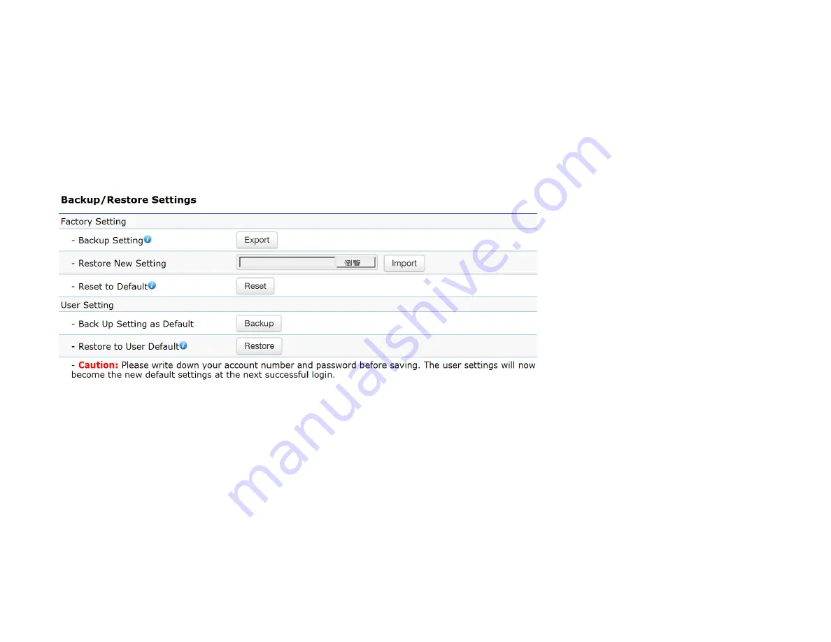
EnGenius EWS550AP User Manual Download Page 83

Backup/Restore 

This page allows you to save the current device configurations. When you save the configurations, you can also reload the sav ed 

configurations into the device through the 

Restore New Settings

 from a file folder. If extreme problems occur, or if you have set 

the Access Point incorrectly, you can use the 

Reset

 button in the 

Reset to Default

 section to restore all the configurations of the 

Access Point to the original default settings. To configure the Backup/Restore Settings, click 

Firmware

 under the 

Systems Manager


tab. 


Factory Setting 

Backup Setting:

 Click 

Export

 to save the current device configurations to a file. 

Restore New Setting:

 Choose the file you wish to restore for settings and click 

Import

Reset to Default:

 Click the 

Reset

 button to restore the Access Point to its factory default settings. 


Summary of Contents for EWS550AP

Page 1: ...EWS550AP version 1 0 Wireless Managed Wall Plate Access Point ...

Page 2: ...cal Interface 12 Chapter 2 13 Considerations for Wireless Installation 14 Computer Settings 15 Hardware Installation 19 Mounting the Access Point 20 Connecting using the 110 Punch down Block 22 Chapter 3 24 Default Settings 25 Web Configuration 26 Chapter 4 28 Device Status 30 Connections 33 Realtime 33 Chapter 5 36 IPv4 Settings 37 IPv6 Settings 38 ...

Page 3: ...46 Wireless Security 48 Wireless MAC Filter 51 Traffic Shaping 52 Fast Roaming 52 Guest Network 54 RSSI Threshold 56 Management VLAN Settings 57 Chapter 7 58 Status 59 Settings 60 Tools 61 Node List 61 Link Status 62 Ping 63 Trace Route 63 Throughput 64 Chapter 8 65 Controller Settings 66 SNMP Settings 66 CLI SSH Settings 69 HTTPS Settings 70 ...

Page 4: ...heduler 73 Tools 75 LED Control 78 Device Discovery 79 Chapter 9 80 Account Setting 81 Firmware Upgrade 82 Backup Restore 83 System Log 84 Reset 86 Logout 87 Appendix 88 Appendix A FCC Interference Statement 89 Appendix B CE Interference Statement 91 ...

Page 5: ...Chapter 1 Product Overview ...

Page 6: ...ity 1 port includes PoE output Supports 802 11ac Wave 2 0 technology to enhance overall bandwidth and speed to wireless client devices Supports Tx Beamforming to enlarge the transmition distance Performs 256 QAM under the 2 4 GHz band to enhance data rate to 400 Mbps Additional RJ45 pass through port for connecting to phone systems Power over Ethernet supports 802 3af output when PoE input is 802 ...

Page 7: ...ffers different encryption settings for wireless communications including industry standard WPA and WPA2 encryption The AP also includes MAC address filtering to allow network administrators to provide network access only to known computers and other devices based on their MAC addresses Maximum data rates are based on IEEE 802 11 standards Actual throughput and range may vary depending on many fac...

Page 8: ...y Windows OS XP Vista 7 8 or Mac OS Linux based operating systems Web browsing application i e Edge Internet Explorer Chrome Firefox Safari or another similar browser application Package Contents The package contains the following items all items must be in package to issue a refund EWS Wall Plate Access Point Mounting Bracket Bracket Screw Quick Installation Guide ...

Page 9: ...oriums amphitheaters classrooms ballrooms arenas exhibition centers or temporary offices where one wants either a permanent or temporary Wireless LAN established The Ability to Access Real Time Information Doctors Nurses Point of Sale Employees and or Warehouse Workers can access real time information while dealing with patients serving customers and or processing information Frequently Changing E...

Page 10: ...2 11ac BPSK QPSK 16 QAM 64 QAM 256 QAM Supported data rates Mbps 802 11b 1 2 5 5 11 802 11a g 6 9 12 18 24 36 48 54 802 11n 6 5 to 400 MCS0 to MCS15 802 11ac 6 5 to 867 MCS0 to MCS9 NSS 1 to 2 Physical Environment Power Source PoE compatible with 802 3af at Supports 802 3af output when PoE input is 802 3at Internal Antenna 4 dBi 5 5 dBi 2 4 GHz antennas 6 dBi 5 3 dBi 5 GHz antennas Interface 1 x 1...

Page 11: ...PMKSA support for fast roaming Security WEP encryption 64 128 152 bit WPA WPA2 Enterprise PSK Hidden SSID MAC address filtering up to 50 MAC Client isolation Management Deployment Options Standalone Mode Managed Mode by Neutron Switch or ezMaster Configuration Web Interface HTTP SNMP v1 v2c v3 with MIB I II and private MIB CLI Telnet Firmware Upgrade Web interface or CLI FTP HTTP Backup Restore Se...

Page 12: ...to factory default settings 3 10 100 1000 LAN Ports Two RJ45 access ports 4 10 100 1000 LAN Port PoE Out RJ45 access port with PoE Out support 802 3af output when PoE input is 802 3at 5 RJ45 Pass Through Port Pass through port 6 10 100 1000 RJ45 Uplink PoE In Uplink port that supports 802 3af at PoE input 7 110 Punch Down Block 3 7 6 1 2 4 5 5 ...

Page 13: ...Chapter 2 Before You Begin ...

Page 14: ...ess Point to have an optimal wireless range during setup Keep the number of walls and or ceilings between the Access Point and other network devices to a minimum Each wall and or ceiling can reduce the signal strength resulting in a lower overall signal strength Building materials make a difference A solid metal door and or aluminum stubs may have a significantly negative effect on the signal stre...

Page 15: ... 7 In order to use the Access Point you must first configure the TCP IPv4 connection of your Windows OS computer system 1 Click the Start button and open the Control Panel Windows XP Windows 7 2a In Windows XP click on Network Connections ...

Page 16: ...iew network status and tasks in the Network and Internet section and then select Change adapter settings 3 Rightclickon LocalAreaConnectionandselectProperties 4 SelectInternetProtocol Version4 TCP IPv4 andthenselectProperties ...

Page 17: ...sdifferentfromtheAccess Point andSubnetmask then clickOK Note Ensure that the IP address and Subnet mask are on the same subnet as the device For example Access Point IP address 192 168 1 1 PC IP address 192 168 1 2 192 168 1 255 PC Subnet mask 255 255 255 0 ...

Page 18: ...Highlight Ethernet 4 In Configure IPv4 select Manually 5 Enter an IP address that is different from the Access Point and Subnet mask then click OK Note Ensure that the IP address and Subnet mask are on the same subnet as the device For example Access Point IP address 192 168 1 1 PC IP address 192 168 1 2 192 168 1 255 PC Subnet mask 255 255 255 0 6 Click Apply when finished ...

Page 19: ...itch or the PoE Out port on the PoE injector 3 Using another RJ45 Ethernet cable connect one end to the Ethernet port on the computer and connect the other end to another port on the PoE Ethernet switch or to the Data In port on the PoE injector 4 Provide power to the PoE injector switch 5 Verify that the Power LED on the AP is steady orange 6 Proceed to set up the Access Point using the computer ...

Page 20: ...ox 1 Remove the cover from the outlet box retaining the original cover screws 2 Gently pull the required cables through the center of the mounting bracket 3 Align the mounting bracket with the outlet box and affix the mounting bracket to the outlet box using the original cover screws ...

Page 21: ...t before mounting it to the bracket 5 Hook the two tabs on the bottom of the bracket into the slots on the bottom of the AP and slide the AP down gently until it holds in place 6 Use the bracket screw provided to secure the AP to the bracket ...

Page 22: ...Connecting using the 110 Punch down block The 110 punch down block can be used to connect the AP to the network instead of the RJ45 connector ...

Page 23: ......

Page 24: ...Chapter 3 Configuring Your Access Point ...

Page 25: ...n will show you how to configure the device using the web based configuration interface Default Settings Please use your Ethernet port or wireless network adapter to connect the Access Point IP Address 192 168 1 1 Username Password admin admin ...

Page 26: ...t LAN IP Address of the Access Point ensure you enter the correct IP Address 2 The default username and password are admin Once you have entered the correct username and password click the Login button to open the web based configuration page 3 If successful you will be logged in and see the Access Point User Interface Model name varies depending on model ...

Page 27: ......

Page 28: ...Chapter 4 Overview ...

Page 29: ...ve and apply the settings shown under Unsaved changes list or Revert the unsaved changes and revert to the previous settings that were in effect The Overview section contains the following options Device Status Connections Real Time ...

Page 30: ...menu shows the status information about the current operating mode The Device Information section shows general system information such as Device Name MAC address Current Time Firmware Version and Management VLAN ID The Memory Information section shows usage of memory such as Total Available Free Cached Buffered ...

Page 31: ...d Spanning Tree Protocal STP status The Wirelesss LAN Information 2 4 GHz 5 GHz section shows wireless information such as Operating Mode Frequency and Channel Since the Access Point supports multiple SSIDs information about each SSID and security settings are displayed Wireless LAN Information 5 GHz only available for 5 GHz capable models ...

Page 32: ... The Statistics section shows Mac information such as SSID MAC address RX and TX ...

Page 33: ... for each client Clicking Kick in the Block column removes this client Click Refresh to refresh the Connection List page Real Time Real Time The Real time section contains the following options CPU Loading 3 minutes CPU loading percentage information it displays current loading average loading and peak loading status Left bar is loading percentage button is time tracing Interval is every 3 seconds...

Page 34: ...Traffic Loading 2 4 GHz and 5 GHz and Ethernet port inbound and outbound traffic by current average and peak time ...

Page 35: ...t active network connections It displays UDP and TCP packet information and other connection status UDP connections curve is in blue TCP connection curve is in green others curve is in red Below the chart shows connections source and destination ...

Page 36: ...Chapter 5 Network ...

Page 37: ...the device IP address will use the static IP address specified in the IP Address field or if it will be obtained automatically when the device connects to a DHCP server IP Address The IP Address of this device IP Subnet Mask The IP Subnet mask of this device Gateway The Default Gateway of this device Leave it blank if you are unsure of this setting Primary Secondary DNS The primary secondary DNS a...

Page 38: ...s IP Address The IPv6 IP Address of this device Subnet Prefix Length The IPv6 Subnet Prefix Length of this device Gateway The IPv6 Default Gateway of this device Leave it blank if you are unsure of this setting Primary Secondary DNS The primary secondary DNS address for this device ...

Page 39: ...another bridge in the spanning tree does not send a hello packet for a long period of time it is assumed to be inactive Forward Delay Specifies Bridge Forward Delay in seconds Forwarding Delay Time is the time spent in each of the Listening and Learning states before the Forwarding state is entered This delay is provided so that when a new bridge comes onto a busy network it analyzes data traffic ...

Page 40: ...hecking this box disables that port If you do not want to provide wired access through the AP uncheck box next to the corresponding LAN port VLAN Check this box to enable VLAN for the LAN port VLAN ID Enter a VLAN ID to segment traffic arriving on this port to a specific VLAN ...

Page 41: ...Chapter 6 2 4 GHz 5 GHz Wireless ...

Page 42: ...nd leave 802 11b g clients in 2 4 GHz to operate at their slower rates Before implementing this feature we suggest you to assure the both 2 4 GHz and 5 GHz SSID as well as security settings must be the same EnGenius Band Steering supports the following advanced settings Force 5 GHz When band steering is configured to Force 5 GHz mode the AP will connect dual band capable client devices to the 2 4 ...

Page 43: ...g is 75dBm Band Balance When band steering is configured to Band Balance mode the AP will steer dual band capable client devices to 5 GHz when the RSSI value of these client devices on the 5 GHz radio is more than set one To evenly allocate RF resource on both the 2 4 GHz and 5 GHz radios users can also set the portion of client devices on 5 GHz radio to assure smoothly connection The default valu...

Page 44: ...wireless broadcasting standard on 2 4 GHz and 5 GHz frequency bands Channel HT Mode Scroll down this list to select the bandwidth for operating under a frequency band The default channel bandwidth is 20 MHz on the 2 4 GHz frequency radio and 40 MHz on the 5 GHz frequency radio Considering the different applications users can decide to implement a channel bandwidth to fulfill real applications The ...

Page 45: ...k but note that the lower the data rate the lower the throughput The though transmission distance is also lowered RTS CTS Threshold Specifies the threshold package size for RTC CTS A small number causes RTS CTS packets to be sent more often and consumes more bandwidth Client Limits Limits the total number of clients on this radio Once you set the ceiling of client numbers allowed the maximum assoc...

Page 46: ...2 4 GHz 5 GHz SSID Profile Under Wireless Settings you can edit the SSID profile to fit your needs Click Edit under the SSID you would like to make changes to ...

Page 47: ...this profile SSID Specifies the SSID for the current profile Security Displays the Security Mode the SSID uses You can click Edit to change the security mode For more details see the next section Hidden SSID Check this option to hide the SSID from clients If checked the SSID will not appear in the site survey Client Isolation Check this option to prevent communication between client devices VLAN I...

Page 48: ...th Type Select Open System or Shared Key Input Type ASCII Regular Text Recommended or HEX Hexadecimal Numbers For advanced users Key Length Select the desired option and ensure the wireless clients use the same setting Your choices are 64 128 and 152 bit password lengths Default Key Select the key you wish to be default Transmitted data is ALWAYS encrypted using the Default Key the other Keys are ...

Page 49: ...me settings Passphrase Wireless clients must use the same Key to associate the device If using ASCII format the Key must be from 8 to 63 characters in length If using HEX format the Key must be 64 HEX characters in length Group Key Update Interval Specify how often in seconds the Group Key changes WPA WPA2 Enterprise Encryption Select the WPA WPA2 encryption type you would like to use Available op...

Page 50: ...ius server Radius Accounting Enables or disables the accounting feature Radius Accounting Server Enter the IP address of the Radius accounting server Radius Accounting Port Enter the port number used for connections to the Radius accounting server Radius Accounting Secret Enter the secret required to connect to the Radius accounting server Interim Accounting Interval Specify how often in seconds t...

Page 51: ...ccess Point The default setting is Disable Wireless MAC Filter ACL Access Control List Mode Determines whether network access is granted or denied to clients whose MAC addresses appear in the MAC address table on this page Choices given are Disabled Deny MAC in the list or Allow MAC in the list MAC Address Enter the MAC address of the wireless client Add Click Add to add the MAC address to the MAC...

Page 52: ...y the changes Fast Roaming Enable the function to serve mobile client devices that roam from Access Point to Access Point Some applications running on Client devices require fast re association when they roam to a different Access Point Please enter the settings of the SSID and initialize the Security mode to WPA enterprise as well as to set the Radius Server firstly Users can enable the Fast Roam...

Page 53: ...Enable Fast Roaming Enable or disable fast roaming feature Enable Advanced Search Enable or disable advanced search feature ...

Page 54: ...D broadcasting SSID Specify the SSID for the current profile This is the name visible on the network to wireless clients Security You can use None or WPA PSK WPA2 PSK security for this guest network Hidden SSID Check this option to hide the SSID from broadcasting to discourage wireless users from connecting to a particular SSID Client Isolation Check this option to prevent wireless clients associa...

Page 55: ...Mask IP Address for the Guest Network Automatic DHCP Server Settings Starting IP Address Specify the starting IP Address range for the Guest Network Ending IP Address Specify the ending IP Address range for the Guest Network WINS Server IP Specify the WINS Server IP Address for the Guest Network WINS means Windows Internet Name Service It is Microsoft s implementation of NetBIOS Name Service NBNS ...

Page 56: ...le the RSSI Threshold feature by ensuring that each client is served by at least one Access Point at any time Access Points continuously monitor the connectivity quality of any client in their range and efficiently share this information with other Access Points in the vincinity of that client to coordinate which of them should serve the client best RSSI Enter the RSSI Received Signal Strength Ind...

Page 57: ...o be physically located next to one another on the LAN Status If your network includes VLANs and if tagged packets need to pass through the Access Point select Enable and enter the VLAN ID Otherwise click Disable Save Click Save to apply the changes Note If you reconfigure the Management VLAN ID you may lose your connection to the Access Point Verify that the DHCP server supports the reconfigured ...

Page 58: ...Chapter 7 Mesh ...

Page 59: ...re with other mesh devices in the system As the wireless environment changes such as the addition of a new node or broken link data paths are re evaluated and the mesh network self tunes automatically to maintain its performance All self tuning processes are dynamic occurring in the background and in real time Status Shows the current status of the mesh network such as Enable Disable Interface ID ...

Page 60: ...ion The system will auto disable the wireless AP function when the user selects the Mesh Point mode Mesh Device Name Click the hyper link to modify the Mesh device s name from the wireless setting page Mesh Band Select the 2 4 GHz or 5 GHz band for the mesh backbone connection Mesh ID The mesh ID should be a maximum of up to 8 characters in numbers 0 9 Password The mesh password should be a maximu...

Page 61: ...nd MAC address Type There are two types of nodes The Root node is uplinked to the gateway by Ethernet wire and connected with other mesh nodes by wireless simultaneously Hops Count Refers to the number of intermediate devices through which data must pass between the Mesh node and Root node If the Hops Count number is more than 3 we recommend that you optimize your deployment of the device s locati...

Page 62: ...gth There are four RSSI levels the signal bar will display If the RSSI is below 76db then it will display a red bar Link Status The Mesh network view is an overview for all mesh nodes Mesh View Mouse over any Mesh node black to see the linking status which is linked to other Mesh nodes blue with a green line Unreachable Mesh Node s The nodes that cannot be connected to the mesh network due to a we...

Page 63: ...ength is continuously lower than the Mesh RSSI in the mesh settings page Detector Nodes The neighbor node s that detect the unreachable mesh node Ping This page allows you to analyze the connection quality of a mesh node to another mesh node in the mesh network Trace Route ...

Page 64: ...you to analyze the routing table to a target from a mesh node to another mesh node in the mesh network Throughput This page allows you to analyze the throughput from a mesh node to another mesh node in the mesh network ...

Page 65: ...Chapter 8 Management ...

Page 66: ...tch or ezMaster SNMP Settings This page allows you to assign the Contact Details Location Community Name and Trap Settings for Simple Network Management Protocol SNMP This is a networking management protocol used to monitor network attached devices SNMP allows messages called protocol data units to be sent to various parts of the network Upon receiving these messages SNMP compatible devices called...

Page 67: ...ss Community Name Read Write Specifies the password for the SNMP community with read write access Trap Destination Address Specifies the port and IP address of the computer that will receive the SNMP traps Trap Destination Community Name Specifies the password for the SNMP trap community SNMPv3 Status Enables or Disables the SNMPv3 feature User Name Specifies the username for the SNMPv3 feature Au...

Page 68: ...Auth Key Specify the Authentication Key for authentication Priv Protocol Select the Privacy Protocol type DES Priv Key Specifies the privacy key for privacy Engine ID Specifies the Engine ID for SNMPv3 ...

Page 69: ... The CLI can be accessed through a command console modem or Telnet connection For security concerns you can enable SSH Secure Shell to establish a secure data communication CLI Status Select Enable or Disable to modify the Access Point via a command line interface CLI SSH Status Select Enable or Disable to modify the Access Point via a command line interface CLI with a secure channel ...

Page 70: ...tocol in and of itself rather it is the result of simply layering the Hypertext Transfer Protocol HTTP on top of the SSL TLS protocol thus adding the security capabilities of SSL TLS to standard HTTP communications Status Select Enable or Disable to modify the Access Point via HTTPS HTTPS Forward Enabling this option will forward the AP modification to HTTPS if the user tries HTTP to access the Ac...

Page 71: ...ow a clearly identifiable email subject Email Account Username Password Enter the username and password required to connect to the SMTP server SMTP Server Port Enter the IP address domain name and port of the SMTP server The default port of SMTP Server is port 25 Security Mode Select the security mode for the Email alert The options are None SSL TLS and STARTTLS Send Test Mail Click Send Test Mail...

Page 72: ...nt s internal clock with the computer s time Automatically Get Date and Time Enter the IP address of a network time protocol NTP server or use the default NTP server to have the internal clock set automatically Time Zone Choose the time zone you would like to use from the drop down list Enable Daylight Savings Check the box to enable or disable daylight savings time for the Access Point Next enter...

Page 73: ...he GMT time setting acquired from an NTP server For details on how to connect the Access Point to an NTP server see Date and Time Settings Auto Reboot Settings Specify how often you would like to reboot the Access Point Status Enables or disables the Auto Reboot function Timer Specifies the time and frequency in rebooting the Access Point by Min Hour and Day ...

Page 74: ...ilable 8 5 daily and Available 8 5 daily except weekends Select Custom schedule if you want to set the schedule manually Day s Place a checkmark in the boxes for the desired days or select the All Week radio button to choose all seven days of the week Duration The Start Time is entered in two fields The first box is for hours and the second box is for minutes The End Time is entered in the same fo...

Page 75: ... table to a target in the network Ping Test Parameters Target IP Domain Name Enter the IP address or Domain name you would like to search Ping Packet Size Enter the packet size of each ping Number of Pings Enter the number of times you wish to ping Start Click Start to begin pinging a target device via IP ...

Page 76: ...Traceroute Parameters Target IP Domain Name Enter an IP address or domain name you wish to trace Start Click Start to begin the traceroute operation Stop Halts the traceroute test ...

Page 77: ... domain name on which you want to run a Speed Test Time Period Enter the time in seconds that you would like the test to run and in how many intervals Start Starts the Speed Test IPv4 IPv6 Port The Access Point uses IPv4 port 5001 and IPv6 port 5002 for the speed test ...

Page 78: ... Enables or disables the Power LED indicator LAN Enables or disables the LAN LED indicator WLAN 2 4 GHz Enables or disables the WLAN 2 4 GHz LED indicator WLAN 5 GHz Enables or disables the WLAN 5 GHz LED indicator Mesh Enables or disables the Mesh LED indicator Click Apply to save the settings after selecting your choices from the boxes ...

Page 79: ...Device Discovery Under Device Discovery choose the Access Point to automatically scan for local devices to connect to Click Scan to begin the process ...

Page 80: ...Chapter 9 System Manager ...

Page 81: ...sername for logging in to the Administrator Username entry box Current Password Enter the old password for logging in to the Current Password entry box New Password Enter the new password for logging in to the New Password entry box Verify Password Re enter the new password in the Verify Password entry box for confirmation Apply Click Apply to save the changes Note It is highly recommended that yo...

Page 82: ... File System to the location of the Firmware upgrade file 2 Select the upgrade file The name of the file will appear in the Upgrade File field 3 Click the Upload button to commence the Firmware upgrade Note The device is unavailable during the upgrade process and must restart when the upgrade is completed Any connections to or through the device will be lost ...

Page 83: ... use the Reset button in the Reset to Default section to restore all the configurations of the Access Point to the original default settings To configure the Backup Restore Settings click Firmware under the Systems Manager tab Factory Setting Backup Setting Click Export to save the current device configurations to a file Restore New Setting Choose the file you wish to restore for settings and clic...

Page 84: ...current settings as the default you should click the Restore to Default on the Web interface for reverting the settings into the factory default instead of pushing the reset button Note2 Please write down your account and password before saving The user settings will now become the new default settings at the next successful login System Log The AP automatically logs records events of possible int...

Page 85: ...ould like to use Remote Log Enables or disables the Remote Log feature If enabled enter the IP address of the Log you would like to remote to Log Server IP Address Enter the IP address of the log server Apply Click Apply to save the changes ...

Page 86: ...ice Once you click the Reset button you will see the options for rebooting or restoring this AP Reboot the device Click to reboot this device Restore to Factory Default Click to reset this device to the factory default settings Restore to User Default Click to reset this device to user default settings ...

Page 87: ...Logout Click Logout it will pop up a warning window Click OK to logout ...

Page 88: ...Appendix ...

Page 89: ... to try to correct the interference by one of the following measures Reorient or relocate the receiving antenna Increase the separation between the equipment and receiver Connect the equipment into an outlet on a circuit different from that to which the receiver is connected Consult the dealer or an experienced radio TV technician for help FCC Caution Any changes or modifications not expressly app...

Page 90: ...equipment complies with FCC radiation exposure limits set forth for an uncontrolled environment This equipment should be installed and operated with a minimum distance of 20 cm between the radiator your body ...

Page 91: ...ion techniques Harmonized EN covering essential requirements under article 3 2 of the R TTE Directive EN 301 893 Broadband Radio Access Networks BRAN 5 GHz high performance RLAN Harmonized EN covering essential requirements of article 3 2 of the R TTE Directive EN 301 489 1 Electromagnetic compatibility and Radio Spectrum Matters ERM ElectroMagnetic Compatibility EMC standard for radio equipment a...

Page 92: ... with the essential requirements and other relevant provisions of Directive 1999 5 EC Español Spanish Por medio de la presente nombre del fabricante declara que el clase de equipo cumple con los requisitos esenciales y cualesquiera otras disposiciones aplicables o exigibles de la Directiva 1999 5 CE Ελληνική Greek ΜΕ ΤΗΝ ΠΑΡΟΥΣΑ name of manufacturer ΔΗΛΩΝΕΙ ΟΤΙ type of equipment ΣΥΜΜΟΡΦΩΝΕΤΑΙ ΠΡΟΣ...

Page 93: ...u jest zgodny z zasadniczymi wymogami oraz pozostałymi stosownymi postanowieniami Dyrektywy 1999 5 EC Português Portuguese Nome do fabricante declara que este tipo de equipamento está conforme com os requisitos essenciais e outras disposições da Directiva 1999 5 CE Slovensko Slovenian Ime proizvajalca izjavlja da je ta tip opreme v skladu z bistvenimi zahtevami in ostalimi relevantnimi določili di...

Reviews: