


162
The electrical installation of ventilation units has to
be left to an authorized electrician.
NOTE
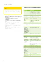
Electrical connection
requirements and preparations
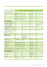
Cf. the electric files at the end of this manual.
Preparing electrical work
Make sure before beginning the installation that:
•
An appropriate main power connection is available for
use for the ventilation unit.
•
Over 30mA residual current protection is in use.
Because of the residual current protection, no other
electric devices can be plugged in the socket.
•
The user has an internet connection, if they want to
use the web interface of the eAir panel.
•
The eAir panel wall mount is installed on wall
mounting box. Keep the eAir panel wall mount
always installed when you use the eAir panel. If you
accidentally touch the circuit board behind the
wall mount with your hand or with an object that
can conduct electricity, the circuit board may be
damaged.
•
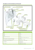
The unit is connected to the control panel with a
cable. Cable must run in a protective pipe with a
minimum diameter of 20 mm. The unit delivery
includes a 10 m cable. A 30-meter cable is available as
an extra. The cable connections are type RJ4P4C.
External sensors:
•
Some ventilation unit models may require certain
outer sensors to be installed.
•
The sensor element of the temperature, humidity and
CO2 sensors must be installed inside the duct. Most
temperature sensors are delivered with a 5-meter long
connection cable. Humidity and CO2 sensors must be
wired locally.
•
The location of the sensor is selected based on
measurements. For more information, see the control
graph at the end of this manual. The location has to
be on the straight part of the duct, and the placement
must be at least twice the diameter of the duct from
the duct coils, turns, or joints.
•
A hole must be drilled into the duct, for the sensor
and the grommet.
•
The sensors connected to the cable are pushed
through a rubber grommet so that the sensor
element is a few centimeters inside the duct. The
rubber grommet must be airtight and tight enough
so that the sensor cable cannot slide through on its
own. It is recommended that the sensor is secured
with a cable tie.
•
Sensors with stiff pipe-like sensor elements are placed
in the duct with an attachable, adjustable flange. The
sensor element is pushed through the flange and
locked in place with a suitable screw.
•
Electrical connections are done based on the
schematics at the end of this manual.
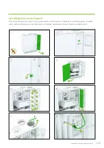
Preparing the eAir control panel wall
mount
eAir control panel must be installed in the wall mount
box. One ventilation unit can be controlled with two
panels at most. Panels can be installed in different wall
mounts or in the same mount. If the panels are installed in
the same wall mount, the other one will need a separate
micro USB charger (not part of the Ensto Enervent unit
delivery).
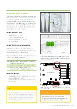
Commissioning two control panels installed
in their own wall mounts.
If the ventilation unit is controlled with two control panels
mounted on different wall mounts, the panels must have
different addresses. The address is selected from the
control board behind the wall mount. One wall mount
has address 1 and the other address 2. We recommend
marking the address both on the wall mount and on the
control panel so that the inhabitants will know which
panel belongs to which wall mount.
Commissioning two control panels
installed in the same wall mount
If the ventilation unit is controlled with two control panels
installed in the same wall mount, the extra panel must
be connected to the wall mount. Connecting is done
by sliding the DIP slide switch two steps down and then
up again. Check for more information from the electric
file on page 206. Connection mode is active, when the
yellow LED light of the control circuit begins to flash. The
connecting mode stays active for 10 minutes. Put the eAir
control pale in the wall mount for a moment, so that the
panel can start. Panel shows that it is trying to connect
Summary of Contents for Pelican eAir
Page 8: ...8 Kanavaliitännät ulkoilma poistoilma jäteilma tuloilma ...
Page 20: ...20 13 15 11 14 Lisävaruste 1 2 min 12 9 10 ...
Page 49: ...49 Ammattilaisen asennusohje ...
Page 52: ...52 Pelican eAir Installationsanvisningar för ventilationsaggregat Svenska ...
Page 58: ...58 Kanalanslutningar uteluft frånluft avluft tilluft ...
Page 70: ...70 13 15 11 14 Extra tillbehör 1 2 min 12 9 10 ...
Page 99: ...99 Installationsanvisningar för yrkesfolk ...
Page 102: ...102 Installeringsinstruksjoner for ventilasjonsenheten Norsk Pelican eAir ...
Page 108: ...108 Kanalanslutningar uteluft avtrekksluft avkastluft tilluft ...
Page 120: ...120 13 15 11 14 Ekstrautstyr 1 2 min 12 9 10 ...
Page 149: ...149 Installasjonsinstrukser for fagfolk ...
Page 152: ...152 Pelican eAir Installation instructions for the ventilation unit English ...
Page 158: ...158 Duct connections outdoor air extract air exhaust air supply air ...
Page 170: ...170 13 15 11 14 Extra 1 2 min 12 9 10 ...
Page 199: ...199 Installation instructions for professionals ...
Page 205: ...205 ...
Page 206: ...206 Enervent Zehnder Oy Kipinätie 1 FI 06150 PORVOO Tel 358 207 528 800 enervent enervent com ...
Page 207: ...207 ...
Page 211: ...211 Enervent Zehnder Oy Kipinätie 1 FI 06150 PORVOO Tel 358 207 528 800 enervent enervent com ...
Page 220: ...220 eAir CG liitännät eAir CG anslutningar eAir CG koblinger eAir CG connections ...
Page 223: ...223 ...


