User Manual
Page 4
2. OPERATION
1
2
3
4
10
5
6
7
8
9
BAR
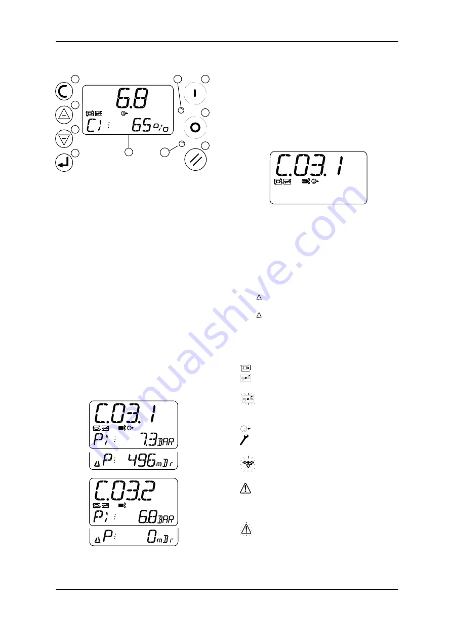
2.1 User Interface
1) LCD
Display
2)
No function (unit always ON)
3)
No function
4)
No function
5) ESCAPE
Button
6)
UP, PLUS Button
7)
DOWN, MINUS Button
8) ENTER
Button
9)
DX Box Active Indicator
10) FAULT
Indicator
2.2 Display
The upper display will continuously show the
The detected ‘System’ pressure and the lower
display will show the percentage load of the
DX Box ‘group’.
Press UP and DOWN to view the status,
‘Delivery’ pressure (if enabled) and
‘Differential’ pressure (if applicable) for each
compressor in the ‘group’.
When viewing the status or pressure
information for a compressor the ‘network
address’ and DX Box identification will be
show on the upper display (for example,
“C.03.1” indicates that the compressor is
connected to the DX Box as compressor #1
and the DX Box is represented on the system
management unit as compressor number
“03”). The status of the compressor will also
be show using the ‘Run’ and ‘Load’ symbols.
If the ‘Delivery’ pressure sensor option for a
compressor has not been enabled the lower
display line will not be shown and the
‘differential’ pressure item will not be available.
User Menu Iems:
P.-C>:
‘System’ Pressure. and % Output
C#1-P>:
‘Delivery’ pressure compressor #1
C#1- P:
‘Differential’ Pressure #1
C#2-P>:
‘Delivery’ pressure compressor #2
C#2- P:
‘Differential’ Pressure #2
2.3 Status Symbols
DX Box Status (C>):
Power Failure Auto Restart (always on)
Communicating with the System
Management Controller (Remote Mode)
Flashing - No Communications with the
System Management Controller (Local
Mode)
One, or both, Compressors are Loaded
One, or both, compressors are switched
to ‘Service Maintenance’ mode.
One, or both, compressors have
exceeded the set Pressure Limit
1: Compressor Alarm
2: Auxiliary Alarm input active
3: Delivery Pressure Sensor fault
(display “- - - -“)
1: Compressor Not Available
2: Auxiliary Trip input active


