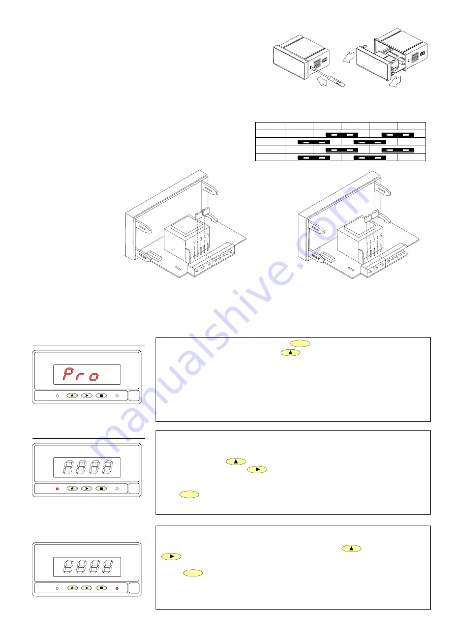
Program setpoint 1 value, LED 1 activated.
The initially programmed value appears on the display with the first digit flashing.
Press repeatedly the
key to increment the active digit from 0 to 9 until it takes
the desired value and press
to advance to the next digit to be modified. Repeat
these operations to complete the desired setpoint value with sign.
Press
ENTER
to validate the entry and pass to the programming of setpoint 2.
[25.2] Setpoint 1
UP
SHIFT
DATA
ENTER
1
2
Program setpoint 2 value, LED 2 activated.
Program the setpoint 2 value with sign by means of the
(change value) and
(change digit) procedure as described in previous phase.
Press
ENTER
to store programmed data in the memory and exit from the
programming mode.
[25.3] Setpoint 2
UP
SHIFT
DATA
ENTER
1
2
To program the setpoint values, press
ENTER
to acceed the programming mode
(indication Pro, figure 25.1) and press
to make the display show the previously
programmed value of setpoint 1.
NOTE: The setpoint values should be programmed within the selected measurement
range.
[25.1] Setpoints Programming
UP
SHIFT
DATA
ENTER
1
2
7
Fig. 9.1. Disassembly.
2.1 – Power supply and connectors
To change the meter’s physical configuration remove the case as
shown in figure 9.1.
115/230 V AC: The instruments with 115/230 V AC power are
set up at fabrication for 230 V AC (USA market 115 V AC), see
figure 9.2. To change power supply configuration to 115 V AC,
make the jumpers indicated in figure 9.3 and table 1. The wiring
label should be modified to match the new configuration.
24/48 V AC: The instruments with 24/48 V AC power are set up
at fabrication for 24 V AC, see figure 9.2. To change power
supply configuration to 48 V AC, make the jumpers indicated in
figure 9.3 and table 1. The wiring label should be modified to
match the new configuration.
12, 24 or 48V DC:
Instruments for DC
power are set up for
the supply voltage
specified in the wiring
label (12V, 24V or 48V
according to the order
reference).
Tabla 1. Jumper settings.
Pin 1 2 3 4 5
230V AC
-
115V AC
-
48V AC
-
24V AC
-
Fig. 9.3. Jumper settings for 115 V or 24 V AC
Fig. 9.2. Jumper settings for 230 V or 48 V AC
23


