background image

Safety Precaution

03

ULTRA CLEAR RESOLUTION CAMERA

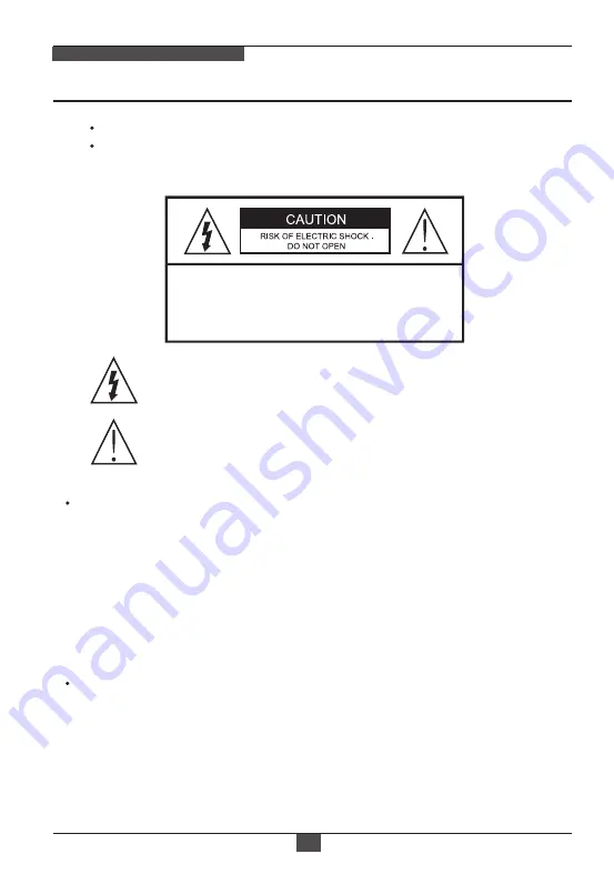
CAUTION: TO REDUCE THE RISK OF ELECTRIC SHOCK,
DO NOT REMOVE COVER (OR BACK). 
NO USER SERVICEABLE PARTS INSIDE.
REFER SERVICING TO QUALIFIED SERVICE PERSONNEL.

To prevent fire or shock hazard, do not expose the unit to rain or moisture.

To prevent electric shocks and risk of fire hazards, do NOT use other than 

specific power source.

The symbol is intended to alert the user to the presence of important        

operating and maintenance(servicing) instructions in the literature 

accompanying the unit.

The symbol is intended to alert the user to the presence of uninsulated

 "dangerous voltage" within the product's enclosure that may be of

sufficient magnitude to constitute a risk of electric shock to persons.


Warning 

:


This equipment has been tested and found to comply with the limits for a Class

 A digital device, pursuant to part 15 of the FCC Rules. These limits are designed

 to provide reasonable protection against harmful interference when the equipment

 is operated in a commercial environment. This equipment generates, uses, and 

 can radiate radio frequency energy and, if not installed and used in accordance with

 the instruction manual, may cause harmful interference to radio communications. 

 Operation of this equipment in a residential area is likely to cause harmful 

 interference in which case the user will be required to correct the interference at 

 his own expense.

 Caution 

 Any changes or modifications in construction of this device which are not expressly

 approved by the party responsible for compliance could void the user's authority 

 to operate the equipment.

 Mains power quality should be that of a typical commercial environment. If the user

 of the model requires continued operation during power mains interruptions, it is 

 recommended that the model be powered from an uninterruptible power supply 

 (UPS) or a battery.

Summary of Contents for MPD-62V2713P0A

Page 1: ...EN User Manual 1 2 8 HD Dome Fixed Indoor Day Night 1920x1080 Infrared 2 7 13 5 mm 12VDC MPD 62V2713P0A ...

Page 2: ......

Page 3: ... A digital device pursuant to part 15 of the FCC Rules These limits are designed to provide reasonable protection against harmful interference when the equipment is operated in a commercial environment This equipment generates uses and can radiate radio frequency energy and if not installed and used in accordance with the instruction manual may cause harmful interference to radio communications Op...

Page 4: ...nection cable and observe that the cable is not subjected to heavy loads kinks or damage and no moisture can get in Never open the device such as boards or lens The warranty becomes void if repairs are undertaken by unauthorized persons Maintenance and repair have to be carried out only by authorized service centers Use only a mild detergent to clean the housing The camera should never be operated...

Page 5: ...OLUTION CAMERA Contents 05 Safety Precaution p 03 04 Contents p 05 Features p 06 Composition p 07 Dimensions p 08 Part Names p 09 Installation Instructions p 10 12 Operating Instructions p 13 30 Specifications p 31 32 ...

Page 6: ...mic Range Improved noise reduction 2D 3D NR TVI mode CVI mode AHD 2DNR CVBS FOCUS ASSIST for Error free focus adjustment 2 Auto AE AWB control LSC Lens Shading Compensation DPC Defective Pixel Compensation Motion detection Privacy mask BLC HSBLC Defog Sens up x30 Mirror Flip Freeze Negative Image IR Smart Cam Title Built in 2pcs High power SMD LED OSD MENU CVBS output for easy installation mainten...

Page 7: ...EAR RESOLUTION CAMERA Mounting Template Operating Instruction Video Sub out Cable Mounting Screw 3 5 x 25mm 3pcs Plastic Anchor 6 x 30mm 3pcs Dome Camera Easy Adaptor Flat type Open Adjust Driver 1pc Easy Adaptor Tilted type ...

Page 8: ... surface while the camera installing or adjusting Care should be taken the cable is NOT to be damaged kinked or exposed in the hazardous area Do not expose the camera directly to a strong light source such as the sun or spot light CAUTION Tilted adaptor Ø116 Ø80 94 with Flat adaptor 52 5 116 3 with Tilted adaptor ...

Page 9: ...UTION CAMERA Part Names 09 Dome Cover Lens Bubble Shield Bubble Dome Base Easy Adaptor Flat type SMD LEDs Focus Zoom adjustment Light Sensor Power Cable 3 Axis Gimbal Tilted Easy Adaptor Video format DIP Switch CVBS HD ...

Page 10: ... Place the Easy Adaptors at the pre drilled installation position and fix it by using mounting screws 3 Route the power video cable to the connecting place 4 Attach the dome base assembly to the Easy Adaptor 5 Adjust the camera s viewing angle Pan Tilt Rotation Then remove the caution sticker Refer to p 11 6 Assemble the dome cover to the dome base unit Open Adjust Driver ...

Page 11: ... camera module is 0 that is the image is aligned horizontally 3 Inclination limit Horizontal image alignment Inclination limited to 60 max 2 5 º 10º 9 0 º Tilted Easy Adaptor EXTENDED VIEWING ANGLE 15 º Zoom focus adjustments Turn the Focus gear until the sharpest focus is made Adjust the zoom for the proper viewing angle Use the open adjust driver supplied Be careful the IR LEDs when you control ...

Page 12: ...structions 12 Detach the dome camera from the easy adaptor Push the hook on the dome base and swing the dome base to counter clock wise Then detach the dome camera from the installed easy adaptor 1 1 2 2 3 Open the dome cover Hold the Dome housing with one hand and turn the open tool until Dome Cover is sufficiently open Insert wide side of Open Tool into the lock of Dome Cover Once Dome Base and ...

Page 13: ...GHT Key Set up the value of the selected menu Used to adjust the desired menu selection and to move the cursor left or right Description of the OSD control operation If OSD menu is adjusted in specific video format adjusted value is applied to only related video format For example if the menu is adjusted in CVBS mode adjusted value is applied to CVBS video only NOTE Using Video Format Switch The D...

Page 14: ...UST 10 EXIT OFF ATW AUTO SAVE END DC Switching video format is available by Video format joystick If you want to set the HD video format set the DIP Switch to HD mode first Then set the one of HD Video format by joystick The default setting is TVI mode JOYSTICK setting 1 TVI mode Up Moving up direction for about 3 seconds to TVI mode 2 CVBS Down Moving down direction for about 3 seconds to CVBS 3 ...

Page 15: ... 30x ON LEVEL 0 8 AUTO OFF OFF AUTO AREA1 4 ON OFF ON OFF 0 100 ALL DAY NIGHT AGC LEVEL MOTION AREA1 4 OFF ON POSITION SIZE 0 100 Green Red White Blue 0 00 1 00 VIEW TYPE OSD VIEW ALARM OUT TIME SELECT DISPLAY SENSITIVITY COLOR TRANS ALARM WHITE BAL DAY NIGHT NR SPECIAL BACKLIGHT ATW AWB MANUAL BLUE RED GAIN OUTDOOR INDOOR AWC SET LEVEL AREA DEFAULT BLC AUTO EXT B W COLOR 2DNR 3DNR AHD only CAM TI...

Page 16: ...RUS POL SPA ITA FRA GER CHN1 CHN2 OFF ON LIVE DPC WHITE DPC BLACK DPC CAM ID ID DISPLAY BAUDRATE FW VER ISP VER AHD RX VER AUTO OFF LDC CRT OFF ON NTSC PAL OFF ON OFF ON AHD TVI mode CVI mode CVBS SELECT DISPLAY COLOR TRANS AGC LEVEL 0 255 LEVEL 0 100 SENS UP POS SIZE START DPC VIEW AGC POS SIZE START DPC VIEW LEVEL LEVEL START AGC END AGC AREA1 4 COLOR INV MOSAIC 0 25 1 00 White User Cyan Green Y...

Page 17: ...is working under florescent or similar lights Lens can be selected either DC or MANUAL lens Lens MUST be set to DC for the best image when DC iris lens is installed 2 FOCUS ASSIST 9 llllllllllllllllllllll OUTDOOR MODE 1 MIN SHU 2 MAX SHU 3 RETURN 1 25 1 2000 RET Usually cameras are installed in the day time and they often become OUT OF FOCUS at night time and IN FOCUS again at next day time This p...

Page 18: ...s DAY NIGHT at the interval of D N DWELL to help the EXACT NIDDLE focus at DAY and NIGHT mode Further simulations are performed internally during switching FLK Reduces the flicker in video when NTSC PAL mode is used in 50Hz 60Hz fluorescent lighting respectively 1 60 1 50 1 30 1 25 x30 x2 1 50000 1 240 Shutter can be set to fix AUTO Optimizes the video level by controlling the iris and the shutter...

Page 19: ...ite pixel accordingly AGC level less than 10 disables AUTO in DAY NIGHT 3 2 AGC 3 5 D WDR CVBS video signal Connecting 2nd video to CVBS port disables D WDR function temporary It should be considered when installer adjusts the video with installation monitor via CVBS video signal Enhance the foggy video according to status of scene Video quality can be less in normal environments Setting to AUTO i...

Page 20: ...ts cutting out Lower setting starts the cut out at lower level The cut out area is masked with black color ALL DAY Enables HS BLC regardless of DAY or NIGHT mode NIGHT Enables HLC only when camera works in NIGHT mode Can be adjusted AGC level 4 1 5 MODE Sets NIGHT only or ALL DAY 4 1 6 DEFAULT Restores to factory default Cuts out the highlight area with black mask and excludes it from compensation...

Page 21: ...ily compensates ATW for high color temperature such as sunlight 5 5 INDOOR Optimized for Indoor installation and more easily compensates ATW for low color temperature such as incandescent lights 5 6 AWC SET WB is performed only whenever is pressed 5 3 MANUAL White balance is fixed to the settings by Red_GAIN and Blue GAIN This mode can be used only when the color temperature does not vary DAY NIGH...

Page 22: ...y at lower higher illumination If it stays in NIGHT B W mode at day time decrease NIGHT DAY threshold value until it just switches to DAY 6 1 2 D N DELAY D N DELAY is time in second while camera maintains its status before Day to Night switches DELAY can avoid the unwanted frivolous switching by a short term lights such as light from the passing car 6 1 4 N D DELAY N D DELAY is time in second whil...

Page 23: ...evel 3DNR 3 dimensional noise reduction which reduces the noise by the multi frames HD format only Noise Reduction is effective at low light Setting high level is strength of noise reduction but the result may occur in loss of sharpness and the tail effect of a comet 8 SPECIAL NR 1 2DNR 2 3DNR 3 RETURN LOW MIDDLE RET NR 1 2DNR 2 RETURN MIDDLE RET video format HD video format CVBS SPECIAL 1 CAM TIT...

Page 24: ...n 8 2 D EFFECT It is relatived picture adjustments 8 3 MOTION OFF Normal display without mirroring or flipping MIRROR Video is reversed left and right V FLIP Video is reversed upside down ROTATE Video is reversed width and length 8 1 CAM TITLE Camera title name can be set and edited up to 15 alpha numeric and symbolic characters moves the cursor and choose a character to select it The selected cha...

Page 25: ...n Red White Blue 8 3 6 ALARM Sets ON or OFF to display the motion results 8 3 5 TRANS Sets transparency rate for the motion block From 0 25 to 1 00 8 3 2 DISPLAY Displays ON OFF the motion area which you selected It can be adjusted position and size 8 3 3 SENSITIVITY Sets the detection sensitivity for motion 0 100 High value increases the sensitivity to detect the small motion easily Too low value...

Page 26: ...ore the current setting to factory default 8 4 PRIVACY OSD VIEW ON enables to display a text message or icon ALARM OUT Not Available VIEW TYPE Selects display type for motion detection ALL Enables to display types both of OUTLINE and BLOCK if motion is detected OUTLINE Enables to display box shape if motion is detected BLOCK Enables to display mosaic shape if motion is detected OFF Disables to dis...

Page 27: ... for white defective pixels POS SIZE Adjusts DPC AREA window size and position START Starts up detecting and compensation DPC VIEW Shows the original defective pixels if set to ON LEVEL Sets the threshold of the detection for white pixels High value increases the video gain in order to show the defective pixels easily Too high value can result in compensation failure AGC Sets AGC level AGC amplifi...

Page 28: ...ue increases the video gain in order to show the defective pixels easily 8 7 RS 485 9 1 SHARPNESS 9 ADJUST CAM ID Assigns the camera ID from 1 255 for the comm address ID DISPLAY Displays CAM ID On or OFF BAUD RATE Selects the baud rate from 2400 115200 Not Available 8 8 VERSION Display F W Version 8 9 COLOR BAR Enable to check the color ADJUST 1 SHARPNESS 2 MONITOR 3 LSC 4 VIDEO OUT 5 MONITOR OUT...

Page 29: ...nes the AGC level to end up for sharpness 9 2 MONITOR Selects LCD or CRT modes the correct type of viewing monitor will ensure the most optimal picture Each monitor type can be adjusted picture quality by BLUE RED GAIN LCD 1 GAMMA 2 BLUE GAIN 3 RED GAIN 4 RETURN USER RET 68 llllllllllllllllllllll 65 llllllllllllllllllllll CRT 1 BLUE GAIN 2 RED GAIN 3 RETURN RET 58 llllllllllllllllllllll 58 lllllll...

Page 30: ...e set it to OFF 9 3 LSC Lens Shade Compensation 9 4 VIDEO OUT Selects HDTV standards for analog video output switches to NTSC or PAL accordingly If the TV standard is changed it is applied to all video format TVI mode CVI mode AHD CVBS 1080P Full HD It takes 3 5 seconds when video format is switching Please check that video format of the DIP Switch on OSD board 9 5 COMET CVBS only Not Available Th...

Page 31: ... 50 000sec Internal More than 52dB with AGC Off at 50 IRE CVBS 59 94Hz V 15 734Khz H 2 1 Interlace CVBS 50Hz V 15 625Khz H 2 1 Interlace HD 30Hz V 22 5Khz H Progressive HD 25Hz V 18 75Khz H Progressive Off H V H V Mirror Flip HD 1080p 30 25 fps CVBS 750TVL CVBS 4 3 750TVL CVBS 4 3 750TVL Focus Assist BLC HSBLC Motion detection Privacy mask Freeze Defog Negative Image IR Smart Cam Title LSC Lens Sh...

Page 32: ...without prior notice Dimension Housing DC12V 470mA 6W Circuit protection against faulty connection in power polarity Double side Anti scratch Hard coated clear bubble Zoom Focus adjustment on 3 Axis gimbal Easy Installation Adaptor Flat Tilted adaptor Ø116mm W x 94mm H _ Bubble Ø80 About 260g Operating Temp 10ºC 50ºC Humidity 20 RH 80 RH ...

Page 33: ......

Page 34: ......

Page 35: ......

Page 36: ... 09 2021 eneo is a registered trademark of Videor E Hartig GmbH Exclusive distribution through specialised trade channels only Videor E Hartig GmbH Carl Zeiss Straße 8 63322 Rödermark Germany Tel 49 0 6074 888 0 Fax 49 0 6074 888 100 www videor com www eneo security com ...

Reviews: