Prothermo NMT 538
14
Hauser Systems & Gauging
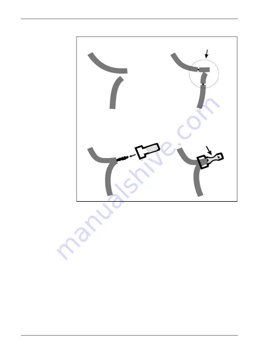
Figure 6: Connector details
Cabling color code is listed below.
NMT 538 cable color: the principle Based on the same as A,B,b 3 wire spot RTD cabling method.
A: Signal wires
No.1: brown (lowest position)
No.2: red
No 3: orange
No. 4: yellow
No. 5: green
No. 6: blue
No. 7: violet
No. 8: gray
No. 9: white
No. 10: pink
No. 11: brown / black
No. 12: red / black
No. 13: orange / black
No. 14: yellow / black
No. 15: green / black
No. 16: blue / black
B: Common wires
B0: gray / black
B1: violet / black
b: white / black
cable from
NMT538
cable from
RTD probe
1. Select a pair cables
A cable from
NMT538
A cable from
RTD probe
2. Strip cable ends
approximately 10mm, or 1/2"
A cable from
NMT538
A cable from
RTD probe
3. Twist both ends together
and install terminal connector
A cable from
NMT538
A cable from
RTD probe
4. Cramp the connected terminal
with pliers or any connector tool
3 Installation


