background image

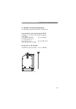
6.2 Measurement point identifier

The front of the unit has three fields that can be filled out.

Filling out individual fields:

-

remove all grease by cleaning the front of the unit (e.g. using spirits).

-

Write on the fields using light proof water resistant markers.

Œ

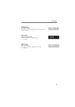
= Description field for engineering units



= Identifier fields

6. Setting up

31

Summary of Contents for mini-log b

Page 1: ...mini log b Unit No 507000 3W Software V2 10 Betriebsanleitung Operating instructions Manuel de mise en service BA 099R 09 a3 01 01 No 510 01241 ...

Page 2: ......

Page 3: ...rät in Betrieb nehmen Gerätenummer Datalogger Operating instructions Please read before installing the unit Unit number Datalogger Mise en service A lire avant de mettre l appareil en service N d appareil Deutsch 1 22 Français 45 66 English 23 44 Datalogger 1 ...

Page 4: ...ung 9 6 3 Gerät ein ausschalten 10 6 4 Batteriewechsel 11 7 Installation der PC Software 12 7 1 Systemvoraussetzungen 12 7 2 Sicherungskopie erstellen 12 7 3 Installationsstart 12 8 Geräteparametrierung per PC Software 13 8 1 Software starten 13 8 2 Geräteeinstellungen festlegen 14 9 Meßwerte verarbeiten 15 9 1 Aktuelle Meßwerte anzeigen 15 9 2 Meßwerte auslesen und darstellen 15 9 3 Meßwerte expo...

Page 5: ...wendung Sicherheitshinweise Der Datalogger hat das Werk in sicherheitstechnisch einwandfreiem Zustand verlassen Ein gefahrloser Betrieb ist nur sichergestellt wenn die Betriebsanleitung beachtet wird Batterien nicht kurzschließen oder mit Fremdspannung überbrücken Explosionsgefahr Batterien nicht verpolt einsetzen Gerätedefekt Verwenden Sie nur Batterien des gleichen Typs Batterien nicht öffnen od...

Page 6: ... Daten im internen Datenspeicher als Momentan oder Min Max Mittelwert abgespeichert werden kontinuierlich oder nur für die Dauer einer Grenzwertverletzung Die Meßwerterfassung erfolgt sekündlich Min Max Mittelwerte werden während der eingestellten Speicherzykluszeit zwischengespeichert und nach Ablauf dieser Zeit in den internen Datenspeicher übernommen Zusätzlich registriert der digitale Eingang ...

Page 7: ... 13 Zubehör und Verbrauchsmaterial 4 1 Wandmontage Montagehalter zur Wandmontage Best Nr 50086642 Öffnen Sie den Gehäusedeckel und schrauben Sie das Gerät nach der Skizze fest 4 2 Rohrmontage Montagehalter zur Rohrmontage Best Nr RDL10A MA Öffnen Sie den Gehäusedeckel und schrauben Sie das Gerät nach der Skizze fest 4 Montage 5 ...

Page 8: ...ise Ist bei langen Signalleitungen mit energiereichen Transienten zu rechnen empfehlen wir die Vorschaltung eines geeigneten Überspannungsschutzes Die Verwendung geschirmter Signalleitungen empfehlen wir bei Widerstandsthermometern Verwendung der seriellen Schnittstelle Achtung Minus der Versorgungsspannung GND Anschluß Pin 4 der Schnittstelle Minus Eingang Klemme 1 des Analog und Klemme 5 des Dig...

Page 9: ...tstelle wird die Batterie schneller entladen Entfernen Sie das Kabel wenn die Schnittstelle nicht genutzt wird oder nutzen Sie die Ausführung mit externer Spannungsversorgung RS 232 7 30 VDC ca 5 mA 1 1 4 5 5 6 6 3 2 1 2 J1 J1 J1 J1 J2 J2 J2 J2 1 3 TTL 5 V Batterieversion Analogeingang Digitaleingang 0 20 mA 4 20 mA 0 1V Pt 100 100 C 400 C potentialfreier Kontakt oder TTL Pegel 5 V Achtung Jumper ...

Page 10: ...t Ë 7 stelliger Zahlenblock Die aktuellen Daten werden als Zahlenblock angezeigt Das Display wechselt in einem 5 sek Anzeigezyklus wie folgt Analogwert Digitalwert Uhrzeit Achtung Je nach Parametrierung der Eingänge kann das Display von diesem Anzeigezyklus abweichen Ist z B kein Digitaleingang aktiviert so wird dieser auch nicht angezeigt In diesem Fall wechselt das Display im 5 sek Zyklus zwisch...

Page 11: ...felder Beschriftung der einzelnen Felder Entfetten und Reinigen Sie die Frontfolie z B mit Spiritus Beschriften Sie die Felder mit einem lichtbeständigen wasserfesten Folienschreiber Ê Beschriftungsfeld für physikalische Einheit Ë Beschriftungsfelder 6 Inbetriebnahme 9 ...

Page 12: ...te des Geräts drücken 4 Funktion des Displays kontrollieren 5 Durch erneutes Drücken des Ein Austasters Ê wird das Gerät wieder ausgeschaltet Achtung Die gespeicherten Daten bleiben auch nach Abschalten des Gerätes im Speicher erhalten Datum und Uhrzeit werden nicht aktualisiert und müssen bei erneutem Einschalten per PC Software eingegeben werden ON OFF Ê Ein Austaster Ë Minusklemme DC Netzversio...

Page 13: ...usschalter Ê abschalten Überprüfen Sie am Display ob das Gerät abgeschalten ist Batterie aus der Halteklammer ziehen Achtung Um einen Datenverlust zu vermeiden schließen Sie innerhalb von 5 min eine neue Batterie an das Gerät an Achtung Achten Sie auf die Polarität der Batterie Bei Verpolung Gerätedefekt Batterie in die Halteklammer drücken Gerät über den Ein Ausschalter Ê einschalten Funktion am ...

Page 14: ...ttstelle 7 2 Sicherungskopien erstellen Erstellen Sie bitte von dem beigelegten Datenträger eine Sicherungskopie 7 3 Installation Installieren Sie die PC Software auf Ihrem Rechner Führen Sie hierzu das Programm install exe vom Datenträger aus und folgen Sie den Anweisungen auf dem Bildschirm Bei Bedarf können Sie die Hilfe Bedienungsanleitung des Programms nach der Installation ausdrucken 7 Insta...

Page 15: ...uf Danach klicken Sie auf Neues Gerät Sie können nun zur genaueren Identifizierung den Gerätenamen den Standort und unter Information zusätzlichen Text eingeben Beenden Sie die Eingabe mit OK Anschließend baut die Software automatisch die Verbindung zum Gerät auf Beim manuellen Einstellen der seriellen Schnittstelle Ihres Rechners klicken Sie auf Vorgabewerte und wählen Ihr Gerät aus Die aktuellen...

Page 16: ...ätenamen definiert haben Die gespeicherten Daten werden aus dem Gerät ausgelesen Gehen Sie mit dem Mauszeiger auf die unter Kapitel Matrix aufgelisteten Eintragungen um nähere Informationen zu erhalten Durch Doppelklicken auf die Eintragungen können sie diese parametrieren Wenn die Parametrierung abgeschlossen ist klicken Sie auf Fertig und speichern die Eintragungen ab 8 Geräteparametrierung der ...

Page 17: ... dem die aktuellen Meßwerte der einzelnen Kanäle dargestellt werden 9 2 Meßwerte auslesen und darstellen Die im Datalogger gespeicherten Daten können über die Schnittstelle RS 232 auf den PC übertragen werden Wollen Sie die Daten nach der Übertragung aus dem Datalogger löschen gehen Sie auf AUSLESEN Meßwerte per Schnittstelle Modem auslesen oder Klicken Sie mit dem Mauszeiger auf die Eintragung di...

Page 18: ...n und wählen Sie anschließend den gewünschten Datalogger aus Es öffnet sich nachfolgendes Fenster Nachdem Sie unter den Menüpunkten AUSWAHL MEßWERTE und FORMATIERUNG die entsprechenden Einstellungen vorgenommen haben bestätigen Sie Ihre Eingabe mit OK Geben Sie den Dateinamen ein unter dem die exportierten Meßwerte gespeichert werden sollen und bestätigen Sie Ihre Eingabe mit OK 9 Meßwerte verarbe...

Page 19: ...echsel hervorgerufen worden sein Verlust der gespeicherten Meßwerte Zählerstände sowie Datum und Uhrzeit Parametrieren Sie das Gerät über die PC Software neu Exx1x keine gültigen Bedienparameter im EEPROM Verlust der Bedieneinstellung Parametrieren Sie das Gerät über die PC Software neu Ex1xx keine gültigen Kalibrierwerte im EEPROM Gerät nicht betriebsbereit Bitte schicken Sie das Gerät zur Repara...

Page 20: ...906 7 388 6 8 h 5440 0 1088 0 2720 0 1813 3 777 1 12 h 10880 0 2176 0 5440 0 3626 7 1554 3 24 h 16320 0 3264 0 8160 0 5440 0 2331 4 Speicherkapazität bei 128k Speicher in Tagen Speicher zyklus Momentan wert Min Max Mittelwert Digitalwert Momentan und Digitalwert Min Max Mittel und Digitalwert 1 min 45 4 9 1 22 7 15 1 6 5 2 min 90 8 18 2 45 4 30 3 13 0 3 min 136 3 27 2 68 1 45 4 19 4 5 min 227 2 45...

Page 21: ...nkabel RS 232 mit 1 5 m Länge ist optional erhältlich Eingang Meßgröße Universell einsetzbar analog Meßumformer muß 0 4 20 mA 0 1 V Signal liefern oder Pt100 Direktanschluß digital potentialfreier Kontakt oderTTL Pegel 5 VDC Anm Der Datalogger besitzt keine Meßumformer speisung Anzahl Eingänge Analogeingang 1 Digitaleingang 1 Meßgenauigkeit Analogeingang 0 1 V Ri 1 MOhm Genauigkeit 0 25 vom Endwer...

Page 22: ...stoff Gehäuse Aluminiumdruckguß Oberfläche pulverbeschichtet Wand Rohrmontagehalter 1 4301 Spannband 1 4301 Elektrischer Anschluß Zweidrahtleitung Dreidrahtleitung bei Pt100 Anschluß über 2 Kabelverschraubungen PG 9 optional 1x Zoll NPT Verschraubung anstelle 1x PG 9 auf Klemmen 2 5 mm2 massiv 1 5 mm2 Litze mit Hülse Anzeige und Bedien oberfläche Anzeige LC Display 7 Segment Vorzeichen Dezimalpunk...

Page 23: ...telle RS 232 Kabellänge 1 5 m mit 9 pol Sub D Stecker Kupplung IP 65 Stecker Schnittstellenkabel RS 232 Best Nr 50086167 für Parametrierung per PC Schnittstellenkabel für Best Nr RDL10A VL Modemanbindung incl Adapter Montagehalter zur Wandmontage Halteplatte aus V2A 1mm Stärke Best Nr 50086642 13 Zubehör und Verbrauchsmaterial 21 ...

Page 24: ...r Pt 100 zur nachträglichen Montage in Kabelverschraubungen Meßbereich 25 C bis 55 C Temperatursensor Pt 100 Best Nr RDL10X TA Lithiumbatterie 3 6 Volt Lithiumbatterie Typ AA Best Nr 51000981 Lithiumbatterie Typ C Best Nr 51000982 Plombiersatz Best Nr RDL10X PA 13 Zubehör und Verbrauchsmaterial 22 ...

Page 25: ...ät in Betrieb nehmen Gerätenummer Datalogger Operating instructions Please read before installing the unit Unit number Datalogger Mise en service A lire avant de mettre l appareil en service N d appareil Deutsch 1 22 Français 45 66 English 23 44 Datalogger 23 ...

Page 26: ...2 Measurement point identifier 31 6 3 Switch unit on off 32 6 4 Changing battery 33 7 PC software installation 34 7 1 System requirements 34 7 2 Make back up copy 34 7 3 Start installation 34 8 Setting up unit using PC software 35 8 1 Start software 35 8 2 Set unit parameters 36 9 Using measured values 37 9 1 Display actual measured values 37 9 2 Read out and display measured values 37 9 3 Export ...

Page 27: ... The data logger has left our works in perfect and safe condition Safe operation can only be guaranteed if all hints and warning notes in these operating instructions are heeded Never short circuit batteries or connecct any external power source to it Danger of explosion Always fit batteries in correct pole direction Danger of unit defect Only use batteries of the same type as installed Do not ope...

Page 28: ...d data is to be stored as instantaneous or min max average values in the built in memory system continuously or only on active set point alarm Every second the measured value is read in Min max average values are stored in a buffer until the end of the measurement cycle At the end of this cycle they are calculated and stored in the internal memory Additionally the digital input records counters ho...

Page 29: ... 13 Accessories and consumables 4 1 Wall mounting Wall mounting installation kit order No 50086642 Open the unit cover and screw the unit to the mounting plate as shown in the diagram 4 2 Stand pipe mounting Stand pipe mounting installation kit order No RDL10A MA Open the unit cover and screw the unit to the mounting plate as shown in the diagram 4 Installation 27 ...

Page 30: ...connection 5 1 Connection hints Should there be a possibility of high energy transients when operating with long cable lengths it is recommended that an overvoltage protector be connected Screened signal cables are recommended when using the following RTDs Using the serial interface Attention Power supply minus GND connetion pion 4 of the interface analogue input minus terminal 1 and terminal 5 of...

Page 31: ...batteries are discharged faster when the serial link is connected Remove the cable when not in use or use the external power version RS 232 7 30 VDC approx 5 mA 1 1 4 5 5 6 6 3 2 1 2 J1 J1 J1 J1 J2 J2 J2 J2 1 3 TTL 5 V Battery version Analogue input Digital input 0 20 mA 4 20 mA 0 1V Pt100 100 C 400 C potential free contact or 5 V TTL peak Attention Jumper J1 upper Jumper J2 lower Attention Jumper...

Page 32: ...ed Ë 7 digit numeric block The actual values are displayed as a numeric block Every 5 seconds the display scrolls as follows Analogue value digital value time Attention Dependent on the unit settings the inputs can be scrolled in a different manner For example should the digital input be inactive then it would not be displayed The display then scrolls from the analogue value to time every 5 second...

Page 33: ... fields that can be filled out Filling out individual fields remove all grease by cleaning the front of the unit e g using spirits Write on the fields using light proof water resistant markers Description field for engineering units Identifier fields 6 Setting up 31 ...

Page 34: ... left side of the unit 4 Check that the display is operational 5 The unit is switched off by operating the on off Ê switch Attention Stored data remain stored in the unit even when it is switched off Date and time however do not continue to operate and must be reset using the PC sotware when the unit is switched on again ON OFF Ê On off switch Ë Minus terminal DC powered version Ì Plus terminal DC...

Page 35: ...f switch Ê Check that the unit is switched off by monitoring the display Pull the battery out of the holding clamp Attention In order to avoid data loss connect a new battery into the unit within 5 min Attention Note battery polarity If incorrect the unit will not operate correctly Push the battery into the battery holder Switch the unit on using the on off switch Ê Check the unit function by moni...

Page 36: ...ee serial interface 7 2 Make back up copy Please first make back up copies of the installation CD ROM supplied 7 3 Installation Install the PC software package onto your computer Run the programme install exe from the CD ROM and follow the on screen instructions If required the help operating manual can be printed out once the software has been successfully installed 7 PC software installation 34 ...

Page 37: ...settings or click Then click New unit For further identification the unit can be described by entering a unit identifier location and any further information required End input by operating OK Now the software automatically makes connection with the respetive unit For manuaI setting up of the PC interface connection the unit type in the default settings displayed on the screen The actual settings ...

Page 38: ...ed under unit identifier The stored values are read from the unit and transferred to the PC software Using the mouse cursor select the required listed entry under Chapter Matrix for further information The entries can be changed by using a double click on individual selections Once setting up has been completed click Finished and save the new entries 8 Setting up unit using PC software 36 ...

Page 39: ...entifier A window is then opened displaying the actual values of individual channels 9 2 Read out and display measured values The values stored in the data logger can be transferred to the PC using the RS 232 interface If you want to delete the values from the data logger go to READOUT position Read out measured values using interface modem or operate Using the mouse cursor select the entry that y...

Page 40: ...n Click menu point SUNDRIES position Export measured values and select the required data logger The following window appears Once the details for SELECTION MEASURED VALUES FORMATTING have been entered acknowledge the entry using OK Enter the filename under which the exported data is to be saved and acknowledge with OK 9 Using measured values 38 ...

Page 41: ...y changing the battery Loss of stored measured values Counter values as well as date and time Set the unit up again using the PC software Exx1x No valid operating parameters in the EEPROM Loss of operating settings Set up the unit again using the PC software Ex1xx No valid calibration values in the EEPROM Unit not ready for operation Please return the unit for repair E1xxx CPU error This means fau...

Page 42: ... 388 6 8 h 5440 0 1088 0 2720 0 1813 3 777 1 12 h 10880 0 2176 0 5440 0 3626 7 1554 3 24 h 16320 0 3264 0 8160 0 5440 0 2331 4 Memory capacity with 128k memory in days Store cycle Instant value Min max average Digital value Instant and digital value Min max average and digital values 1 min 45 4 9 1 22 7 15 1 6 5 2 min 90 8 18 2 45 4 30 3 13 0 3 min 136 3 27 2 68 1 45 4 19 4 5 min 227 2 45 4 113 6 ...

Page 43: ...a complete RS 232 interface cable 1 5 m long is optionally available Inputs Input Universal application analogue transmitter must have 0 4 20 mA 0 1 V output signal or direct Pt100 digital potential free contact or 5 VDC TTL peak Note The Datalogger has no loop power supply Number of inputs Analogue input 1 Digital input 1 Accuracy Analogue input 0 1 V Ri 1 MOhm Accuracy 0 25 FSD 0 4 mA 20 mA via ...

Page 44: ...ie cast surface galvanised Wall stand pipe adapter 1 4301 Strap 1 4301 Electrical connections Two wire connection three wire on Pt 100 Connection access using 2 PG 9 cable glands optionally 1 x NPT thread instead of 1 x PG9 Termination on 2 5 mm2 terminals 1 5 mm2 core with ferrule Display and operating level Display LC Display 7 segment prefix decimal point limit symbol battery status symbol Oper...

Page 45: ...he RS 232 serial interface Cable length 1 5 m with 9 pole Sub D plug IP 65 plug RS232 interface cable for PCs Order code 50086167 Interface cable for Order code RDL10A VL modems incl adaptor Wall mounting kit Base plate in stainless steel thickness 1 mm Order No 50086642 13 Accessories and consumables 43 ...

Page 46: ...perature sensor for retro fitting into cable entry Measurement range 25 C to 55 C Pt 100 temperature sensor Order No RDL10X TA 3 6 Volt lithium battery Lithium battery Type AA Order No 51000981 Lithium battery Type C Order No 51000982 Lead seal kit Order No RDL10X PA 13 Accessories and consumables 44 ...

Page 47: ...ät in Betrieb nehmen Gerätenummer Datalogger Operating instructions Please read before installing the unit Unit number Datalogger Mise en service A lire avant de mettre l appareil en service N d appareil Deutsch 1 22 English 23 44 Français 45 66 Datalogger 45 ...

Page 48: ...ors tension de l appareil 54 6 4 Remplacement de la pile 55 7 Installation du PC logiciel 56 7 1 Matériel nécessaire 56 7 2 Copie de sauvegarde 56 7 3 Installation 56 8 Paramétrage de l appareil avec PC logiciel 57 8 1 Lancement de PC logiciel 57 8 2 Définition des réglages de l appareil 58 9 Traitement des valeurs mesurées 59 9 1 Affichage des valeurs mesurées instantanées 59 9 2 Lecture et repré...

Page 49: ...reil ou altérer son fonctionnement 2 Utilisation conforme à l objet conseils de sécurité Le data logger a quitté nos établissements dans un état technique parfait Un fonctionnement sans danger n est garanti que si les instructions sont scrupuleusement respectées Les fils de raccordement de la pile ne doivent pas entrer en contact sinon risque d explosion Veiller à la bonne polarité sinon risque d ...

Page 50: ...ire interne comme valeurs instantanées minima maxima et moyennes Les valeurs mesurées sont enregistrées toutes les secondes Avant d être transmis à la mémoire interne les minima maxima et moyennes figurent dans une mémoire tampon en fonction du cycle de sauvegarde programmé L entrée digitale enregistre par ailleurs des comptages par ex le nombre la durée de fermetures de contact Après traitement d...

Page 51: ...13 accessoires et con sommables 4 1 Montage mural Support pour montage mural réf 50086642 Ouvrez le couvercle du boîtier et serrez les vis comme le montre le schéma ci dessous 4 2 Montage sur conduite Support pour montage sur conduite réf RDL10A MA Ouvrez le couvercle du boîtier et serrez les vis comme le montre le schéma ci dessous 4 Montage 49 ...

Page 52: ...cas de risque de transients puissants sur des câbles de si gnal longs prévoir un branchement à un parafoudre L utilisation de câbles de signal blindés est conseillée avec les thermorésistances l interface sérielle Attention Le pôle négatif de la tension d alimentation la terre broche 4 de l interface le pôle négatif borne 1 de l entrée analogique et la borne 5 de l entrée digitale sont reliés entr...

Page 53: ...interface sérielle est raccordée Retirer le câble si elle n est pas utilisée ou utiliser la version avec alimentation externe RS 232 7 30 VDC ca 5 mA 1 1 4 5 5 6 6 3 2 1 2 J1 J1 J1 J1 J2 J2 J2 J2 1 3 TTL 5 V Entrée analogique Entrée digitale 0 20 mA 4 20 mA 0 1V Pt 100 100 C 400 C contact sans potentiel ou niveau TTL 5 V Attention J1 en haut J2 en bas Attention J1 en bas J2 en bas Raccordement 2 f...

Page 54: ...les 5 secondes l écran affiche les informations suivantes Valeur analogique Valeur digitale Heure Attention Ce cycle peut être différent en fonction du paramétrage des entrées Par exemple une entrée n est pas affichée si elle n est pas active et dans ce cas l écran affiche la valeur analogique et l heure toutes les 5 secondes Ì Repères de seuil L appareil peut surveiller deux seuils en interne qui...

Page 55: ...a face avant possède deux zones d inscription Inscription Dégraissez et nettoyez la face avant par ex avec de l alcool Utilisez un feutre résistant aux U V et étanche à l eau Ê Zone pour l unité physique Ë Zone de texte 6 Mise en service 53 ...

Page 56: ...si l affichage fonctionne correctement 5 Appuyer de nouveau sur la touche de gauche Ê l appareil est de nouveau hors tension Attention les données sont conservées dans la mémoire même après mise hors tension de l appareil La date et l heure ne sont pas mises à jour il faut les entrer dans PC logiciel après une nouvelle mise sous tension Ê Touche Ë Borne version DC Ì Borne version DC ON OFF Ê DC 7 ...

Page 57: ... Mettre l appareil hors tension avec la touche Ê S assurer à l écran que l appareil est bien hors tension Appuyer sur les ressorts de la pile dégager cette dernière Attention Pour éviter une perte de données installez la nouvelle pile en moins de 5 minutes Attention Veiller à la polarité de la pile risque d endommagement en cas d inversion Installer la pile Mettre l appareil sous tension avec la t...

Page 58: ...face sérielle libre 7 2 Copie de sauvegarde Faire une copie de sauvegarde de la CD ROM d installation livrée 7 3 Installation Installer le logiciel sur l ordinateur Pour ceci exécuter le pro gramme install exe de la CD ROM et suivre les instructions affichées à l écran Le cas échéant il est possible d imprimer les instructions d aide après installation du program me 7 Installation du PC logiciel 5...

Page 59: ...cliquer sur Puis cliquer sur nouvel appareil Pour une meilleure identifica tion il est possible d entrer le nom de l appareil le lieu et du texte dans Information A la fin cliquer sur OK Pour le réglage de l interface sérielle de l ordinateur cliquer sur les valeurs de présélection et sélectionner l appareil Les valeurs utilisées par le data logger sont automatiquement réglées et enregistrées S as...

Page 60: ...tion de l appareil avec le pointeur de la souris Les données mémorisées sont copiées dans PC logiciel Pour obtenir des informations détaillées diriger le pointeur de la souris sur une entrée de la liste Chapitre matrice L entrée est paramétrée après un double clic Une fois le paramétrage terminé cliquer sur OK et mémori ser l entrée 8 Paramétrage de l appareil avec PC logiciel 58 ...

Page 61: ...e définie sous identification appareil La fenêtre dans laquelle figurent les valeurs mesurées instantanées des diverses voies s ouvre 9 2 Lecture et représentation des valeurs mesurées Les données mémorisées dans le data logger peuvent être transmises vers le PC via l interface sérielle RS 232 Si l on souhaite lire les données du data logger après le trans fert il faut aller sur LECTURE lecture mé...

Page 62: ... EXCEL Cliquer sur DIVERS exporter données EXCEL puis sélectionner le data logger La fenêtre suivante s affiche Après les diverses sélections dans SELECTION VALEURS MESUREES et FORMATAGE confirmer avec OK Entrer le nom du fichier des valeurs exportées et confirmer avec OK 9 Traitement des valeurs mesurées 60 ...

Page 63: ...aleurs mesurées mémorisées des états de compteur de la date et de l heure Reparamétrer l appareil avec PC logiciel Exx1x Les paramètres de service contenus dans l EEPROM ne sont pas valables Perte des réglages Reparamétrer l appareil avec PC logiciel Ex1xx Les valeurs d étalonnage contenues dans l EEPROM ne sont pas valables L appareil n est pas prêt à fonctionner Retourner l appareil au service E...

Page 64: ...7 388 6 8 h 5440 0 1088 0 2720 0 1813 3 777 1 12 h 10880 0 2176 0 5440 0 3626 7 1554 3 24 h 16320 0 3264 0 8160 0 5440 0 2331 4 Capacité d une mémoire de 128k en jours Cycle de mémorisation Valeur instantanée Min Max moyenne Valeur digitale Valeur instantanée et digitale Min max moyenne val instant et digit 1 min 45 4 9 1 22 7 15 1 6 5 2 min 90 8 18 2 45 4 30 3 13 0 3 min 136 3 27 2 68 1 45 4 19 4...

Page 65: ...iverselles Analogique le transmetteur doit posséder une sortie 0 4 20 mA 0 1 V ou Pt 100 Digitale contact sans potentiel ou niveua TTL 5 VDC Remarque Le Datalogger ne dispose pas d alimentation deux fils Nombre d entrées Entrée analogique 1 Entrée digitale 1 Précision Entrée analogique 0 1 V Ri 1 MOhm Précision 0 25 de la fin d échelle 0 4 mA 20 mA par shunt Ri 50 Ohm surveillance de rupture de câ...

Page 66: ...m x 100 mm x 60 mm Poids env 0 5 0 7 kg selon construction Matériau Boîtier fonte d aluminium surface galvanisée Plaque pour montage mural acier inox 304 Collier de serrage acier inox 304 Raccordement électrique Raccord deux fils trois fils sur Pt 100 Entrée de câble 2 x PE 9 bornes 2 5 mm fil 1 5 mm avec férule Affichage et niveau d exploitation Affichage Affichage LCD 7 segments préfixe point dé...

Page 67: ...eur de câble 1 5 m avec connecteur submin D 9 broches connecteur IP 65 Câble d interface RS 232 réf 50086167 pour le paramétrage de l appareil Câble d interface réf RDL10A VL pour liaison modem Support pour montage mural Plaque de maintien en V2A épaisseur 1 mm réf 50086642 13 Accessoires et consommables 65 ...

Page 68: ...10A MA Sonde de température Pt 100 pour montage ultérieur Gamme de température 25 C à 55 C Thermorésistance Pt 100 réf RDL10X TA Pile lithium 3 6 V type AA Pile lithium type AA réf 51000981 Pile lithium type C réf 51000982 Kit de plombage réf RDL10X PA 13 Accessoires et consommables 66 ...

Page 69: ...13 Accessoires et consommables 67 ...

Page 70: ...13 Accessoires et consommables 68 ...

Page 71: ......

Page 72: ...Beijing Tel 0 10 68 34 40 58 Fax 0 10 68 34 40 68 Asia Endress Hauser GmbH Co Shenyang Tel 0 24 22 79 14 95 Fax 0 24 22 79 00 55 China Endress Hauser Shanghai Instrumentation Co Ltd Shanghai Tel 0 21 54 90 23 00 Brazil Samson Endress Hauser Ltda Sao Paulo Tel 011 Fax 011 50 31 30 67 50 31 30 67 Canada Endress Hauser Ltd Endress Hauser Chile Ltd Burlington Ontario Tel 905 6819292 Fax 905 6819444 Ch...

Reviews: