


Micropilot FMR66B HART
Hauser
V. 1, Rev. 2, 26-07-2022
15
• Digital: 1 mm
• Analog: 1 µA
Response time
According to DIN EN IEC 61298-2 / DIN EN IEC 60770-1 , the step response time is the time
following an abrupt change in the input signal up until the changed output signal has adopted 90 %
of the steady-state value for the first time.
The response time can be configured.
The following step response times apply (in accordance with DIN EN IEC 61298-2 / DIN EN IEC
60770-1) when damping is switched off:
• Pulse frequency ≥ 5/s (cycle time ≤ 200 ms)
at U= 10.5 to 35 V, I= 4 to 20 mA and T
amb
= –50 to +80 °C (–58 to +176 °F)
• Step response time < 1 s
Influence of ambient
temperature
The output changes due to the effect of the ambient temperature with respect to the reference
temperature.
The measurements are performed according to DIN EN IEC 61298-3 / DIN EN IEC 60770-1
Digital output (HART)
Average T
C
= 3 mm/10 K
Analog (current output)
• Zero point (4 mA): average T
C
= 0.02 %/10 K
• Span (20 mA): average T
C
= 0.05 %/10 K
Mounting
Mounting location
A
1
2
3
A0016883
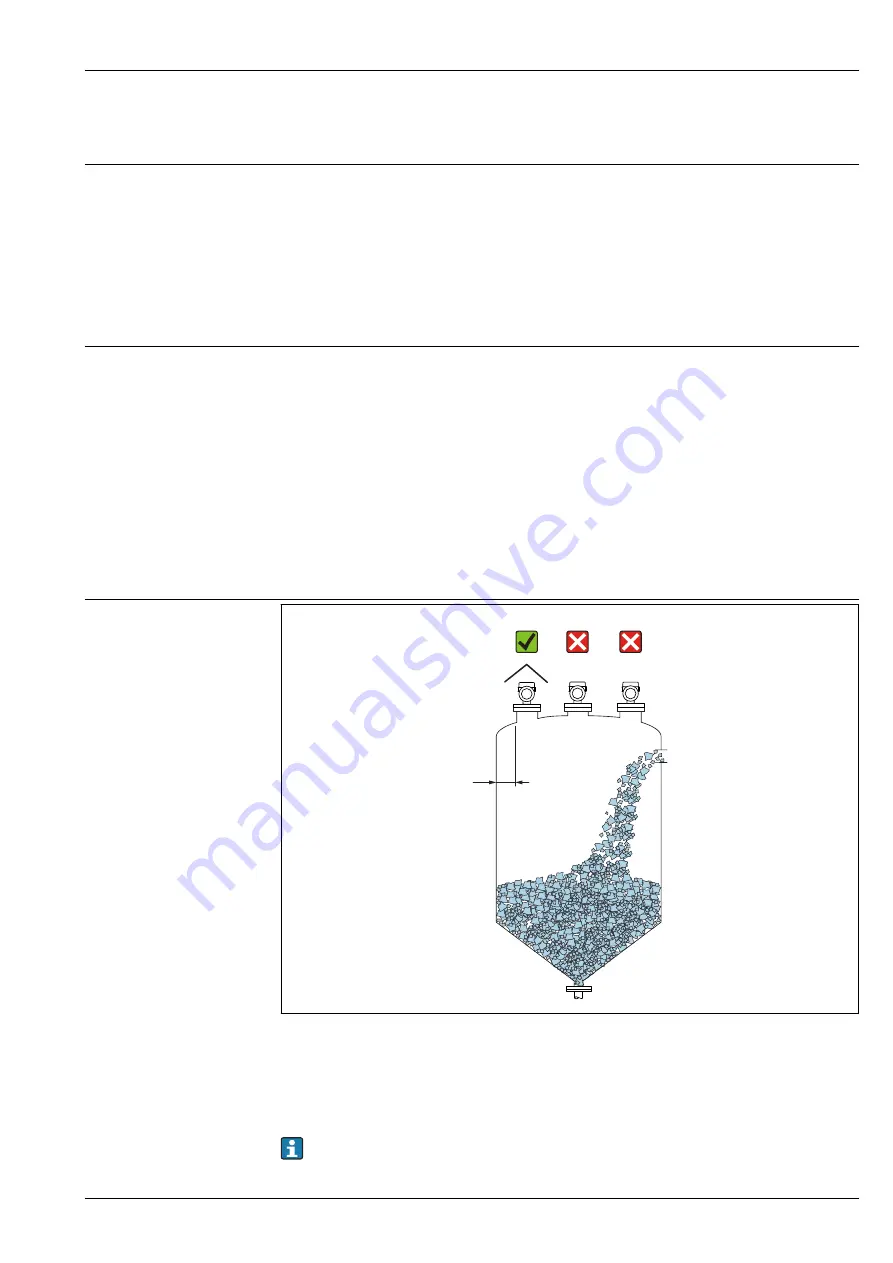
A
Recommended distance from wall to nozzle outer edge ~ 1/6 of the vessel diameter. The device should never
be mounted closer than 20 cm (7.87 in) to the vessel wall.
1
Use of a weather protection cover; protection from direct sunlight or rain
2
Installation in the center, interference can cause signal loss
3
Do not install above the filling curtain
In applications with strong dust emissions, the integrated purge air connection can prevent the
antenna from becoming clogged.


