


Cerabar M, Deltabar M, Deltapilot M / 4...20 mA HART
Commissioning
Hauser
79
6.10.3
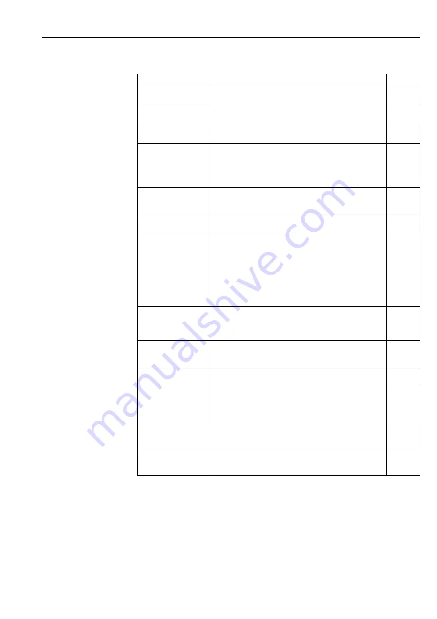
Setup menu for the "Flow" measuring mode
Parameter name
Description
see page
Lin./SQRT switch (133)
Display
Displays the status of DIP switch 4 on the electronic insert, which is used
to define the output characteristics of the current output.
Measuring mode (005)
Selection
Select the "Flow" measuring mode.
Pressure side switch (163)
Display
Indicates whether the "SW/P2High" DIP switch (DIP switch 5) is switched
on.
High pressure side (006)
(183)
Selection
Determines, which pressure input corresponds to the high-pressure side.
!
Note!
This setting is only valid if the "SW/P2High" DIP switch is in the OFF
position (see the "Pressure side switch" (163) parameter). Otherwise P2
corresponds to the high-pressure side in any case.
Press. eng. unit (125)
Selection
Select the pressure unit.
If a new pressure unit is selected, all pressure-specific parameters are
converted and displayed with the new unit.
Corrected press. (172)
Display
Displays the measured pressure after sensor trim and position adjustment.
Pos. zero adjust (007)
Selection
Position adjustment – the pressure difference between zero (set point) and
the measured pressure need not be known.
Example:
– Measured value = 2.2 mbar (0.033 psi)
– You correct the measured value via the "Pos. zero adjust" parameter
with the "Confirm" option. This means that you assign the value 0.0 to
the pressure present.
– Measured value (after pos. zero adjust) = 0.0 mbar
– The current value is also corrected.
Max. flow (009)
Entry
Enter maximum flow of primary element.
See also layout sheet of primary element. The maximum flow is assigned to
the maximum pressure which you enter via the "Max. pressure flow"
(010) parameter.
Max. pressure flow (010)
Entry
Enter maximum pressure of primry element.
See layout sheet of primary element. This pressure is assigned to the
flow defined in the "Max. flow" (009) parameter.
Damping switch (164)
Display
Displays the status of DIP switch 2 "damping
", which is used to switch
the damping of the output signal on and off.
Damping value (017)
Entry/Display
Enter damping time (time constant
). The damping affects the speed at
which the measured value reacts to changes in pressure.
!
Note!
The damping is only active if DIP switch 2 "damping
" is in the ON
position.
Flow (018)
Display
Displays the present flow value.
Pressure after damping
(111)
Display
Displays the measured pressure after sensor trim, position adjustment and
damping.


