background image

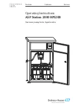
ASP Station 2000 RPS20B

Document information

Hauser

5

1.2.1  

Symbols on the device

Symbol

Meaning

Reference to device documentation

Summary of Contents for ASP Station 2000 RPS20B

Page 1: ...Products Solutions Services Operating Instructions ASP Station 2000 RPS20B Stationary sampler for liquid media BA01324C 07 EN 02 19 71431888 2019 02 15 ...

Page 2: ......

Page 3: ...0 6 Electrical connection 21 6 1 Connecting the sampler 21 6 2 Ensuring the degree of protection 24 6 3 Post connection check 25 7 Operation options 26 7 1 Structure and function of the operating menu 26 7 2 Access to the operating menu via the local display 26 8 Commissioning 28 8 1 Function check 28 8 2 Switching on 28 8 3 Quick Setup 29 8 4 Configuring the tap calibrating 30 8 5 Manual setting ...

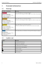
Page 4: ...erous situation Failure to avoid the dangerous situation can result in a fatal or serious injury LCAUTION Causes consequences If necessary Consequences of non compliance if applicable Corrective action This symbol alerts you to a dangerous situation Failure to avoid this situation can result in minor or more serious injuries NOTICE Cause situation If necessary Consequences of non compliance if app...

Page 5: ...ASP Station 2000 RPS20B Document information Endress Hauser 5 1 2 1 Symbols on the device Symbol Meaning Reference to device documentation ...

Page 6: ...into one or several sampling containers and stored in a cool place The sampler is designed for use in the following applications Communal and industrial wastewater treatment plants Laboratories and water management offices Use of the device for any purpose other than that described poses a threat to the safety of people and of the entire measuring system and is therefore not permitted The manufact...

Page 7: ... it is safe to operate The relevant regulations and European standards have been observed Devices connected to the sampler must comply with the applicable safety standards 2 5 2 IT security We only provide a warranty if the device is installed and used as described in the Operating Instructions The device is equipped with security mechanisms to protect it against any inadvertent changes to the dev...

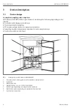
Page 8: ...ing PE or glass sample bottles for sample preservation Sampling chamber temperature regulator for safe sample storage Suction line with suction head 1 2 3 4 5 6 7 A0022775 1 Example of an ASP Station 2000 RPS20B 1 Vacuum system dosing system with conductive sample sensor 2 Controller 3 Distribution arm 4 Sample bottles e g 2 x 12 PE 1 liter bottles 5 Bottle trays depending on sample bottles select...

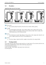
Page 9: ...ker until it reaches the conductivity probes of the dosing system 3 Dose The intake process ends Depending on the position of the dosing tube item D the excess sample liquid flows back to the sampling point 4 Drain The hose clamp is opened and the sample is drained into the sample bottle 3 3 Dosing system The sample liquid is extracted discontinuously by a vacuum system The vacuum system in the AS...

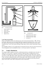
Page 10: ...es place via the shorter conductivity sensor item 1 The sampling volume is set by adjusting the dosing tube item 4 between 20 ml and 200 ml The dosing system can be dismantled easily no tools are needed and cleaned 3 4 Sample distribution The sample liquid is distributed into the individual bottles by a distribution arm item A In addition to a 30 l and 60 l composite container different bottle con...

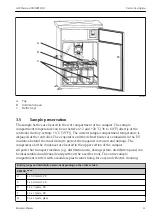
Page 11: ...rost heater are embedded in the PU insulation behind the inner lining to protect them against corrosion and damage The compressor and the condenser are located in the upper section of the sampler All parts that transport medium e g distribution arm dosing system distribution pans can be disassembled and cleaned easily without the need for tools The entire sample compartment is fitted with a seamle...

Page 12: ...vice description ASP Station 2000 RPS20B 12 Endress Hauser Bottle groups and distribution versions depending on the order version RPS20B L 4 x 20 l direct PE N 4 x 12 l direct PE S 12 x 1 8 l plate glass ...

Page 13: ...he best protection Make sure to comply with the permitted ambient conditions If you have any questions please contact your supplier or your local Sales Center LCAUTION Incorrect transportation may result in injuries or damage to the device Transport the sampler using suitable lifting equipment e g pallet truck or forklift truck Do not lift the sampler by the roof 4 2 Product identification 4 2 1 N...

Page 14: ...this window as well as the product documentation 4 3 Scope of delivery The scope of delivery comprises ASP Station 2000 RPS20B with The ordered bottle configuration Optional hardware Connection nipple for suction line Brief Operating Instructions in the language ordered Optional accessories Operating Instructions in other languages can be downloaded on the product page 4 4 Certificates and approva...

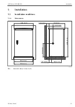
Page 15: ...0B Installation Endress Hauser 15 5 Installation 5 1 Installation conditions 5 1 1 Dimensions 880 34 7 735 28 9 100 3 94 185 7 28 1295 51 0 880 34 7 854 33 6 442 17 4 123 4 84 610 24 0 A0022685 4 Standard cabinet in mm inch ...

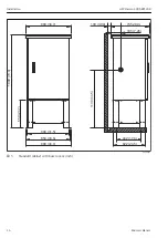
Page 16: ...lation ASP Station 2000 RPS20B 16 Endress Hauser 880 34 7 735 28 9 100 3 94 185 7 28 880 34 7 854 33 6 800 31 5 622 24 5 442 17 4 1800 70 9 1130 44 5 550 21 7 A0022686 5 Standard cabinet with base in mm inch ...

Page 17: ...3 94 166 6 54 228 8 98 304 12 0 160 6 30 854 33 6 920 36 2 221 8 70 280 11 0 442 17 4 800 31 5 Ø 80 3 15 Ø 80 3 15 Ø 80 3 15 Ø 10 0 39 E M10 4x A0022682 6 Foundation plan for standard cabinet with and without base dimensions in mm inch A Fasteners 4 x M10 B Cable duct C Drain for condensation D Hose entry bottom option E Drain for overflow ...

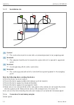
Page 18: ...th an upward gradient to the sampling point Note the following when erecting the device Erect the device on a level surface Protect the device against additional heating e g from heaters Protect the device against mechanical vibrations Protect the device against strong magnetic fields Make sure air can circulate freely at the side panels of the cabinet Do not mount the device directly against a wa...

Page 19: ...urbulent flow not directly at the bottom of the channel Useful sampling accessories Suction filter Impedes coarser solids and solids which can cause clogging Immersion assembly The adjustable immersion assembly fixes the suction line at the sampling point 5 2 Installation 1 When installing the device take the installation conditions into account 2 Lay the suction line from the sampling point to th...

Page 20: ... h When the sampling cycle begins one of the relay outputs can be used to control and open ball valve 2 The medium flows through the pipe and the flow assembly and into the outflow Once an adjustable delay time has elapsed the sample is taken directly from the flow assembly Ball valve 2 is closed again once the sample has been taken The ball valve and the diaphragm valve are not included in the sc...

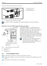
Page 21: ...t label it as the circuit breaker for the device The ground connection must be made before all other connections Danger may arise if the protective ground is disconnected 6 1 1 Laying the cable Lay the cables so that they are protected behind the rear panel of the device Cable glands up to 8 depending on the version are available for the cable entry The cable length from the foundation to the term...

Page 22: ...ng screws 2 Lift the cabinet roof at the front 3 Pull the cabinet roof forwards and lift You can now remove the rear panel Removing the rear panel 1 2 A0023444 1 Release the securing screws 2 Lift the rear panel up and remove it The terminal board and the terminal strip in the electronics compartment are now exposed for wiring ...

Page 23: ...terminal strip in the electronics compartment Connect the supply voltage at the terminal strip in accordance with the following assignment PIN Assignment PE Protective ground provided by customer L1 Phase provided by customer N Neutral wire provided by customer PE Optional protective ground 45 Optional phase 46 Optional neutral wire ...

Page 24: ...wing signals to the terminals 3 digital input signals 20 ms 1 analog input signal 0 to 1 V 0 to 20 mA or 4 to 20 mA 3 relay output signals 6 2 Ensuring the degree of protection Only the mechanical and electrical connections which are described in these instructions and which are necessary for the required designated use may be carried out on the device delivered Exercise care when carrying out the...

Page 25: ... instructions in this manual Put the transmitter into operation only if you can answer yes to all questions Device condition and specifications Are the sampler suction line and all cables undamaged externally Electrical connection Are the mounted cables strain relieved Have the cables been routed without loops and cross overs Have the signal lines been connected correctly in accordance with the wi...

Page 26: ...pling programs ESC Exit the menu level ON or OFF Switch the device on and off The Off key has different functions depending on whether a program has been started or not If a program has not been started The device is switched off If a program is running Pressing the Off key briefly approx 1 s sets the program to break mode If the key is pressed for a longer period 1 s the running program is termin...

Page 27: ...REP Displays the report list Events are logged in this list while the device is switched on A maximum of 30 reports are saved The reports are stored in a ring memory If the ring memory is full and a new report occurs the oldest report is deleted STAT Bottle statistics of the sampler The device displays the statistics for each individual bottle after the program startup In this way you can draw con...

Page 28: ... connections have been established correctly in accordance with the wiring diagram Ensure that the supply voltage matches the voltage indicated on the nameplate 8 2 Switching on 1 Switch on the supply voltage The display starts to light up and displays the message UNIT OFF 2 Press the operating key below the ON field The message UNIT ON appears The device is in operation and you can perform the Qu...

Page 29: ...p prog end time no START PROGR start aut Esc â á Switch unit on with ON In SETUP select QUICK SETUP using the right hand push button Using the right push button change to SET Select SET Select one of the 4 main programmes Select sample mode Select the required distribution mode The bottle change is done dependent on time number of samples taken or by an active external signal Enter the number and ...

Page 30: ...e tap is positioned exactly in the notch in the middle of the distribution pan 4 Select SAVE The tap is calibrated 8 5 Manual setting of sample volume The required sample volume is set by moving the dosing pipe manually Check which sample volume is set in the active program a b 1 2 300 350 400 450 500 3 1 Stop or pause any sampling programs running 2 Release the clamping lever and air tube a Pull ...

Page 31: ... 02 unit off on man aut off set rep stat setup Quick Setup Info Basic Settings Basic Settings Program Selection Name ASP2000 Creating Programmes Code 0000 Service Date Time Esc â á Sampling Inputs Inputs Output Thermostat Digital1 no Interfaces Digital2 sampling Esc â á Digital3 bottle Analog quantity ext Esc â event report A0023634 EN 12 Menu structure Sampling The input signal triggers a sample ...

Page 32: ... the configured main program Stop Aut The input signal ends the configured main program Switch The input signal triggers a switch to the switching program For the described functions a digital signal must be assigned to digital input 1 2 or 3 23 Analog input Inputs Digital Input 2 Digital Input 3 Analog Input Analog Input no 0 20mA Esc â á signal 4 20mA units l s dec point XXX X range 100 0 l s Es...

Page 33: ...vent of sampling Bottle The output contact is switched in the event of a bottle change Ext stop The output contact is switched in the event of an external stop Fill end The output contact is switched when the sampling program is stopped No flow The output contact is switched if the device was unable to draw in any sampling medium e g blocked intake hose CS 1 2 The output contact is switched in the...

Page 34: ...device draws in sampling medium and doses Overfill The output contact is switched when a bottle is overfull Paral sample PN The output contact is switched in the event of an active parallel program Event prg The output contact is switched in the event of an active event program Switch prg The output contact is switched in the event of an active switching program 9 2 3 Program selection A0023637 EN...

Page 35: ...tching program and the event program are active The changeover from the main program to the switching program can be triggered as follows Day Change to the switching program at two configurable times in one day Week Change to the switching program on three configurable days in a week Q greater Change to the switching program when the value exceeds a configurable threshold An analog signal must be ...

Page 36: ...s of the sampler for this function The digital input must be configured with the QUANTITY function for this purpose Ext sign Sampling is triggered by an external signal One of the digital inputs must be assigned and configured with the SAMPLE function Flow Sampling is triggered at configurable intervals The sample volume taken is proportional to a flow currently measured The ASP Station 2000 must ...

Page 37: ... sign The tap switches to the next empty bottle when an external signal is present A digital input must be assigned and configured with the BOTTLE function Start stop operation A0023640 EN 18 Menu structure The sampling program can be started either immediately by pressing the AUT key or at a configurable time The end of the sampling program can be defined as follows Program end The device stops s...

Page 38: ...ic filling times For example bottle 1 could be filled from midnight 00 00 to 2 a m bottle 2 from 2 a m to 4 a m etc The following options are available for this AUT key The sampling and bottle change times are not synchronized Time Sampling starts with the first bottle The change to the next bottle is synchronized Example a time of 2 hours was set for the bottle change and midnight 00 00 was the t...

Page 39: ...ved for the switching programs With the exception of parallel sampling the following applies when distributing to bottles The first bottle group of a distribution is reserved for the main programs The second bottle group is reserved for the switching programs The last bottle group is reserved for the event program A0023646 EN 21 Menu structure The bottles for the switching program can be defined a...

Page 40: ...gram Program 4 Creating Programmes switch 1 Service switch 2 Esc â á event program A0023647 EN 22 Menu structure Sampling mode event program Sample Sample time Distribution mode time quantity Parallel sample time 00 15 ext sig volume 100ml flow shots 01 once Esc â Esc â á A0023648 EN 23 Menu structure The same sampling options that are available in the main programs and switching programs time pac...

Page 41: ... 24 Menu structure The bottles for the event program can be defined as follows No change There is no bottle change when the system switches to the event program Move The next empty bottle is filled when the system changes to the event program 1 9 bottles When the system switches to the event program 1 9 bottles are filled from the last distribution bottle group The number of bottles that can be re...

Page 42: ... main switching or event program Distribution A bottle change is time controlled in the parallel program For parallel sampling 1 x separate bottles referred to as reserve bottles below must be reserved A0023662 EN 26 Menu structure The position of the bottles for the parallel sample can be defined at the start from vessel 1 in the center before the bottles of the switching and event programs or at...

Page 43: ...o Parallel sampling is stopped automatically when the last reserve bottle has been filled Parall end When the last reserve bottle is filled parallel sampling continues automatically with the first reserve bottle Prog end When the main program is completed parallel sampling continues automatically at the first reserve bottle ...

Page 44: ...not find the zero position Replace the air manager if necessary have repaired by Service ERROR Tap zero point Tap defective or jammed Check the tap if necessary replace the distribution system or have repaired by Service ERROR Distributor missing Distributor not connected to controller Check the connector of the distributor if necessary have repaired by Service ERROR 4 20mA 3mA Analog signal trans...

Page 45: ...nnel Sample not representative Siphon in sampling hose Connection not tight sampling hose drawing in air Bottles not filling correctly Distributor tap stuck Incorrect bottle filled No sample cooling Check the sampling hose Check hoses connections Check routing of the sampling hose Incorrect distribution selected in operation Calibrate the tap Check the distribution connection Distributor defective...

Page 46: ...0023665 1 Membrane pump set of gaskets 2 years 2 Air manager 2 years 3 Air filter 1 year 4 O ring seals 1 year 5 Dosing glass 1 year 6 Diaphragm for hose clamp 1 year 11 2 Cleaning 11 2 1 Device Only use cleaning agents that will definitely not damage the mechanical and electrical device components We recommend stainless steel cleaner for the cabinet body and water or soap if applicable for the pa...

Page 47: ...m a b 1 2 300 350 400 450 500 3 1 Release the clamping lever and air tube a Pull the dosing glass b forwards and remove it 2 Open the bayonet lock and open the dosing glass 3 Clean the dosing glass and the dosing glass cover with conductivity probes thoroughly with water or soap 4 Then re install the dosing glass in the reverse order ...

Page 48: ... 4 pull forwards out of the frame Rinse with water or soap 4 Remove the bottle trays item 5 Clean the bottles and bottle trays with water or soap 11 2 3 Sample compartment The sample compartment has a continuous inner plastic lining Once the bottle trays distribution pan and tap have been removed the entire sample compartment can therefore be cleaned with a water hose 11 2 4 Fan liquefier The fan ...

Page 49: ...air Endress Hauser 49 12 Repair 12 1 Spare parts A0023670 28 Spare parts A Electronics compartment after roof installation B Dosing system Item Designation Order number 1 Housing no spare part 2 Kit RPS20B Roof cpl 316 x 71257657 ...

Page 50: ...B Pump membrane set EPDM 71257669 16 Kit RPS20B Pump membrane set Viton 71257677 17 Kit RPS20B Air manager complete 71257679 18 Kit RPS20B Air manager tubing set 71257681 None Kit RPS20B Vaporizer 71257665 Kit RPS20B Retrofit kit internal light 71257703 Kit RPS20B Small maintenance kit 71257707 Kit RPS20B Maintenance kit pump 71257710 19 Kit RPS20B Equipment couplings 71257680 Kit RPS20B Sample fe...

Page 51: ...ng handle bolt cpl 71257693 32 Kit RPS20B Rotary tap drive cpl 71257699 33 Kit RPS20B Rotary tap cpl adapter 71257700 Kit RPS20B Adapter rotary tap 71257698 None Kit RPS20B Cable set rotary tap 71257701 Kit RPS20B Terminal board 71257702 Kit RPS20B Air filter for membrane pump 71257688 Kit RPS20B Dosing hose 15x2 71259919 12 2 Return The sampler is repaired on site Contact your Endress Hauser Serv...

Page 52: ...71251031 Kit RPS20B distribution pan 12 bottles Order no Bottles covers 71111164 1 liter 0 26 US gal PE cover 24 pcs 71111165 1 liter 0 26 US gal glass cover 24 pcs 71134277 1 8 liter 0 48 US gal glass cover 6 pc 71111167 3 liter 0 79 US gal PE cover 12 pcs 71251036 12 l 3 2 US gal PE cover 1 pc 71251038 20 l 5 3 US gal PE cover 1 pc 71111172 30 liter 7 92 US gal PE cover 1 pc 71111173 60 liter 15...

Page 53: ...and with stand cover 71119408 Flow assembly sample 14 Technical data 14 1 Power supply See the Electrical connection section 21 14 1 1 Supply voltage 200 to 240 V AC 50 60 Hz Mains fluctuation 10 Mains fuse Max 10 A 14 1 2 Power consumption 355 VA 14 1 3 Overvoltage protection Overvoltage category 2 14 2 Environment Pollution level 2 14 2 1 Ambient temperature 20 to 40 C 0 to 100 F 14 2 2 Storage ...

Page 54: ...zed 14 4 Mechanical construction 14 4 1 Design dimensions 15 14 4 2 Weight Approx 110 kg 242 lbs 14 4 3 Materials Not in contact with medium Cabinet housing V2A AISI 304 optionally V4A AISI 316 Sample compartment inner lining PS Insulation PU CO2 foamed In contact with medium Intake hose EPDM Hose connection PP POM PA Dosing tube PVC Dosing beaker cover PP Dosing beaker PMMA Conductivity electrode...

Page 55: ... Hauser 55 In contact with medium Distribution pans PS Composite container bottles PE optionally glass Pneumatics Hoses Silicone Air Manager housing PC Air Manager sealing plate Silicone Vacuum pump head Aluminum anodized Vacuum pump membrane EPDM ...

Page 56: ...Supply voltage 53 D Degree of protection 24 Designated use 6 Device description 8 Device design 8 Diagnostics 44 Digital inputs 31 Display 26 Disposal 51 Distribution 37 39 41 42 Dosing system 9 E Electrical connection 21 Electrical safety 54 Electromagnetic compatibility 53 Environment 53 Event program 40 F Flow assembly 19 Function 9 I Incoming acceptance 13 Installation Installation 19 Installa...

Page 57: ...R Removing the cover 21 Removing the rear panel 21 Repair 49 Return 51 S Safety instructions 6 Sample distribution 10 Sample preservation 11 Sample volume 30 Sampling mode 36 39 40 42 Scope of delivery 14 Start stop operation 37 Storage temperature 53 Supply voltage 53 Switching on 28 Switching program 39 Symbols 4 5 Synchronization 38 T Tap 30 Technical data Environment 53 Mechanical construction...

Page 58: ......

Page 59: ......

Page 60: ...www addresses endress com 71431888 71431888 ...

Reviews: