


HS 55 (Batch Mode)
Installation and commissioning
33
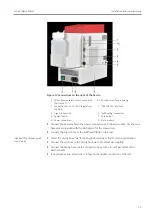
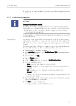
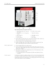
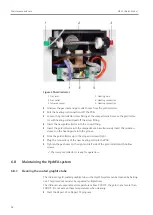
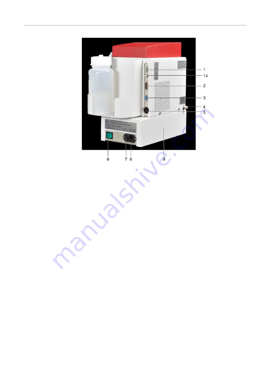
Figure 18Connections on the right of the device
1 Cell unit temperature sensor connection
("cell sensor")
1a Knurled screw for grounding
2 Connection for +5 V/+24 V supply from
the AAS
3 "AAS/RS 232" interface
4 Argon connection
5 "cell heating" connection
6 Power switch
7 Fuse holder
8 Power connection
9 Basic module
}
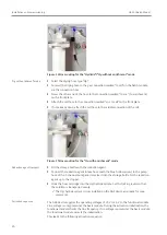
Connect the power cable to the power connection on the basic module. Use the mul-
tiple socket provided with the AAS device for the connection.
}
Connect the Argon hose to the bulkhead fitting on the rear.
}
Connect the HydrEA hose to the coupler on the connection marked "to cell" of the
batch module and plug it onto the titanium cannula of the AS-GF.
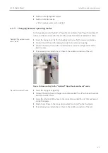
Reduction agent transport
}
Fill the storage bottle with the reduction agent.
}
Connect the reduction agent intake hose (with the blue hollow screw) to the pump
hose of the 1-channel pump and immerse it into the storage bottle for the reduction
agent up to the stopper.
}
Hook the hose cartridge into the Hg/hydride system. Set the locking levers so that
the solution is transported evenly.
ü
The Hg/hydride system is now installed on the AAS device and ready for mea-
surements.
Activation sequence
The AAS device supplies the operating voltages of +5 V/+24 V to the functional module.
Line voltage is only present at the basic module. During the activation initialization, the
functional module checks the line frequency. If no voltage is present at the basic module,
the functional module cancels the initialization.