background image

06

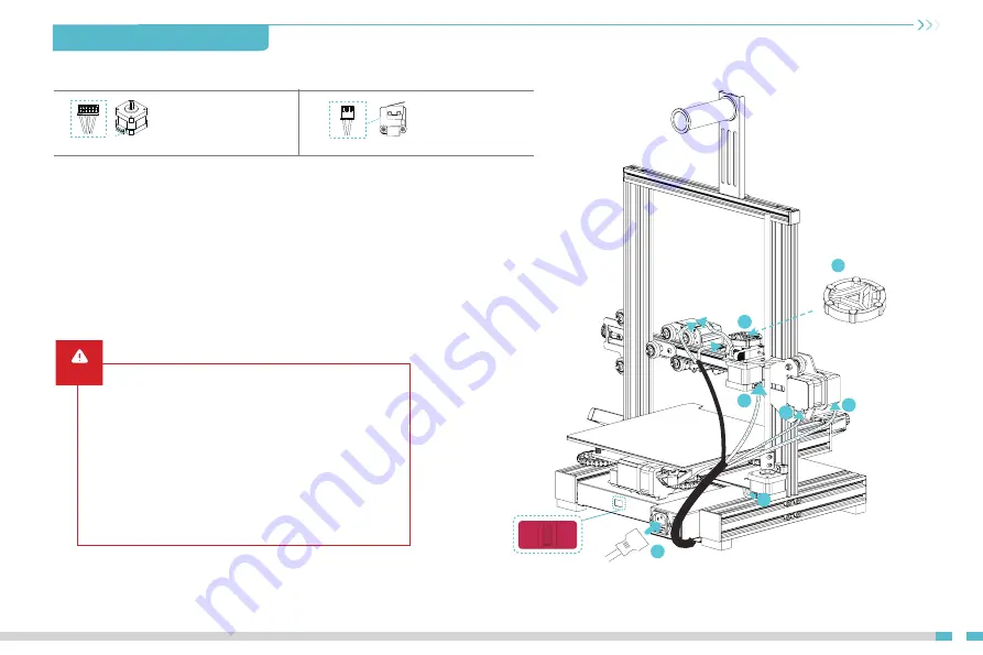
4.4 Cable Connection

X, E, Z-axis motor port

6pin (4 wires)

3pin (2 wires)

X-axis limit switch

A.


Put the indication knob directly onto the motor shaft;

B1.


Follow the yellow label on the 6pin (4 wires) port to connect the X-axis stepper motor;

B2. 

Follow the yellow label on the 6pin (4 wires) port to connect the E-axis stepper motor;

B3. 

Follow the yellow label on the 6pin (4 wires) port to connect the Z-axis stepper motor;

C.


Follow the yellow label on the 3pin (2 wires) port to connect the X axis limit switch;

D.


Plug in the power cord and toggle the switch to turn on the power.


Caution

Before powering on, be sure to select the correct 

voltage mode according to the local grid voltage 

to avoid burning out the power supply;

If the local power grid voltage is within 200-240V, 
please dial the power supply of the machine to 230V 
(it is 230V by default).

If the local power grid voltage is within 100-120V, 

please dial the power supply of the machine to 115V;

115V

230V

B2

B1

C

D

B3

A

14

4. Installing the 3D Printer

Summary of Contents for 3 V2 Neo

Page 1: ...3D Printer User Manual V1 0 Create reality achieve dreams Ender 3 V2 Neo Ender 3 V2 Neo...

Page 2: ...f this manual to contact us To further improve your user experience you can nd more about our devices via the following methods User manual You can nd instructions and videos in the memory card provid...

Page 3: ...complete please use tools to clean up the lament on the nozzle while the nozzle is still hot Do not touch the nozzle with your hands when cleaning otherwise your hands may get burned Please regularly...

Page 4: ...Table of Contents About the Printer 01 01 Device Speci cations 02 02 List of Accessories 03 03 04 07 Installing the 3D Printer 08 12 Using the 3D Printer 13 13 First Printing 14 14 Circuit Wiring...

Page 5: ...aterial rack and material barrel 8 Z axis passive block 9 X axis tensioner 10 Display screen 11 Rotary switch 12 Voltage regulation gear 13 Y axis limit switch 14 Y axis motor 15 Indication knob 17 X...

Page 6: ...int Method FDM Molding tech Number of nozzles Supported slice software Input voltage Rated power Hotbed temperature 250 C Yes Nozzle temperature Power loss recovery English Espa ol Deutsche Fran ais P...

Page 7: ...em Cutting Plier 5 Wire Clip Blue 6 Filament 20mm 12 Wrench and Screwdriver 7 Power Cable 8 Nozzle Cleaner 9 Storage Card Card Reader 10 Nozzle 11 Indication Knob 14 Quick Release Claw 15 M5x45 Hexago...

Page 8: ...x45 hexagon socket head spring washer combination screws from the bottom to the top C Rotate the bottom component by 180 to ensure that the pro les on both sides are level Use two M5x45 hexagon socket...

Page 9: ...the side of the right pro le snap it into the pro le in parallel and tighten the screws B Connect the display screen wiring 4 4 3 Installing material rack A Fix the material rack and barrel assembly t...

Page 10: ...stepper motor C Follow the yellow label on the 3pin 2 wires port to connect the X axis limit switch D Plug in the power cord and toggle the switch to turn on the power Caution Before powering on be s...

Page 11: ...is pulley adjustment Gently turn the pulley to check whether it is idling or jammed If this phenomenon occurs use an open end wrench to adjust the tightness of the hexagonal eccentric isolation column...

Page 12: ...tion the printer will return to the home position again and the levelling process is complete Go to Prepare Z o set adjust the Z axis compensation value so that the height of the nozzle to the printin...

Page 13: ...6 Auxiliary levelling 09 6 2 Go to Prepare Auto home to return to the starting position 6 1 Go to Control Reset con guration to reset the printer parameters 0 00 Leveling Leveling...

Page 14: ...value so that the height of the nozzle to the platform is almost the thickness of A4 paper 0 08 0 1mm then click the knob and the central point leveling is done 6 4 6 3 Go to Prepare Move Move Z and...

Page 15: ...t extrusion even scraping the platform Filaments are extruded evenly just sticking on the platform Adjust the knob at the bottom of the hotbed and move the nozzle to the four corners of the printing p...

Page 16: ...r the laments inside the nozzle to soften then press the extrusion handle and pull out the laments quickly to prevent them from getting stuck at the heat break B Replace the new laments onto the mater...

Page 17: ...rs Close 8 5 Launch the Creality Slicing Software 8 6 Load the le 8 7 Select the le Creality Slicer Load 8 9 Insert the memory card Press the screen knob Select from the menu Select the used for print...

Page 18: ...rd slot Controllable fan port Fuse Power input jack NO fan port Hotbed cable port Nozzle cable port Filament detection port X axis limit switch por Y axis limit switch port Z axis limit switch port No...

Page 19: ...Please refer to the actual product The nal interpretation right belongs to Shenzhen Creality 3D Technology Co Ltd 18F JinXiuHongDu Building Meilong Blvd Longhua Dist Shenzhen China 518131 O cial Websi...

Reviews: