background image

– Page 15 –

iSaver DPFC 165 & 250 Series Manual

© 2021 Encorp Limited

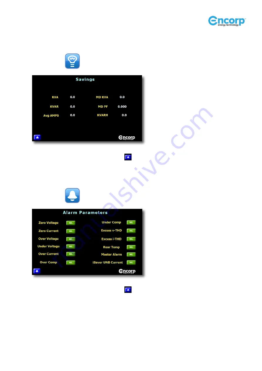
Savings Parameter:

Touch this icon 

  and the Savings Parameter screen will appear.

To return to the HOME screen, touch this icon 

Alarm Parameters:

Touch this icon 

  and the Savings Parameter screen will appear.

To return to the HOME screen, touch this icon 


Summary of Contents for iSaver 160A

Page 1: ...OPERATING MANUAL iSAVER DPFC 165 250 Series The Eliminator ...

Page 2: ...Manual 2021 Encorp Limited TABLE OF CONTENTS Section 1 Introduction 3 Section 2 Specifications 6 Section 3 Installation 9 Section 4 Start up 11 Section 5 Periodic Maintenance 25 Section 6 Troubleshooting 26 Section 7 Limited Warranty 32 ...

Page 3: ...tions within the unit becoming loose It is mandatory to internally inspect the unit and tighten any loose connections prior to installation and start up Depending on the environment and site conditions the unit should be periodically inspected internally by a qualified electrical technician Introduction Majority of the loads in commercial establishments industrial processes have very rapidly chang...

Page 4: ...he internal design is fully accessible and inspection checks and any routine maintenance are logical and easy Extremely easy to install with its own multi indicator practically no maintenance requirement The Power and Energy meter enable monitoring of actual consumption and other parameters Short circuit and overload protection provided through MCB or MCCB Over temperature protection is provided b...

Page 5: ...ls In such applications the reactive power demand is almost instantaneous and the iSaver DPFC is designed to compensate within few milliseconds that requirement and maintain the Power Factor close to unity To select the correct size of iSaver DPFC it is a good practice to measure the maximum reactive power requirement as well as Voltage and Current Harmonics so that the correct size of equipment c...

Page 6: ...rements Controller Micro controller based advanced electronic controller Target Efficiency 98 3 Energy Monitoring HMI Module with IP controller board Displayed Data RMS V I kVA kW Hz kWh PF kVAR Hz KVARh saved kVAh lag THDv THDi Deg F Display Meter Zero Voltage current Over Voltage current Over Under compensation Under Volt Excess VTHD ITHD iSAVER UNB Current Diagnostics Phase CT Sequence Indicato...

Page 7: ...ller based advanced electronic controller Target Efficiency 98 3 Energy Monitoring HMI Module with IP controller board Displayed Data RMS V I kVA kW Hz kWh PF kVAR Hz KVARh saved kVAh lag THDv THDi Deg F Display Meter Zero Voltage current Over Voltage current Over Under compensation Under Volt Excess VTHD ITHD iSAVER UNB Current Diagnostics Phase CT Sequence Indicator Short circuit and Over load p...

Page 8: ...e iSAVER Rating Rating of Main Incoming Breaker Suggested Minimum Cable rating 3 5 core Suggested Cable Rating GND Neutral iSAVER 160A iSAVER 240A 250A 500A 212 KCmil Copper Cable 400 KCmil Copper Cable Per regulatory requirements Based on maximum current rating of the iSAVER incoming breakers ...

Page 9: ... as to avoid entry of unwanted pests All cables to the iSAVER should be routed through the rubber gourmet and the gland reinstalled Turn down the power from the main power supply to the facility and ensure it is not energized and safe to connect Ensure the main breaker of the distribution board and iSAVER breakers are in an OFF position Select approved CT size based on the capacity of the Main Pow...

Page 10: ...les in the right sequence Use only an approved cable with suitable sizing for connecting from the main distribution to the iSAVER MCCB as shown in the connection schematic Connect Ground for iSAVER with an approved cable of a suitable size Color coding as per required electrical standards and codes is to be followed It is extremely important to ensure that the external CT primary value is entered ...

Page 11: ... up Procedure The iSAVER has an advanced HMI display on the front iSaver panel providing the following displayed pages on the home screen These icons provide the following functions Live Dashboard Touch this icon to view the live dashboard which displays mains and load parameters ...

Page 12: ...ouching the next screen icon Mains Power Touch the arrow icon for the next screen to appear Touch this icon for the previous screen to appear Mains VAF Parameters Touch the arrow icon for the next screen to appear Touch this icon for the previous screen to appear Touch the online button to display the instant parameters ...

Page 13: ...xt screen to appear Touch this icon for the previous screen to appear Mains Power Quality Touch the arrow icon for the next screen to appear Touch this icon for the previous screen to appear Demand Parameters Touch the arrow icon for the next screen to appear Touch this icon for the previous screen to appear ...

Page 14: ...eters Touch the arrow icon for the next screen to appear Touch this icon for the previous screen to appear iSaver Parameters Touch this icon for the previous screen to appear To view the Savings Alarm and Live Dashboard screens touch the icon and the screen below will appear ...

Page 15: ... Limited Savings Parameter Touch this icon and the Savings Parameter screen will appear To return to the HOME screen touch this icon Alarm Parameters Touch this icon and the Savings Parameter screen will appear To return to the HOME screen touch this icon ...

Page 16: ...corp Limited Configuration Screen To return to the HOME screen touch this icon Touch this icon to view the Configuration screen Password for 165KVAR machine 165 Password for 247 5KVAR machine 250 Touch the PASSWORD field and a numeric table will appear ...

Page 17: ...appear To change the numeric values touch the existing field value and a numeric table will appear Enter the new value and press the blue Enter button The new value will be stored in system memory Touch the arrow icon for the next Configuration screen to appear To return to the HOME screen touch this icon Touch any of the numeric fields to change the values ...

Page 18: ...emory Touch the arrow icon for the next screen to appear Touch this icon for the previous screen to appear To return to the HOME screen touch this icon To change either the Calendar or Clock values you need to change each of the numeric fields independently i e DD MM YY To view the OPERATIONAL SEQUENCES select this field To change the OPERATIONAL SEQUENCE values touch this field and enter a value ...

Page 19: ...ES button and the existing energy value will be cleared Click the LOGOUT to display the live dashboard This will display the machine performance Auto manual Operation Select the blue HOME icon then touch the AUTO MANUAL icon in the top right corner of the screen The Auto Manual screen will then appear Select the blue HOME icon then touch the AUTO MANUAL icon in the top right corner of the screen T...

Page 20: ...ual check to ensure that it is safe to start commissioning the iSAVER all connections secured tools removed and safety checks completed Turn on the breakers within the iSAVER unit Close the iSAVER main access panel door and secure the panel locks with the key provided Turn ON the main incomer MCCB located on the exterior front panel door of the iSAVER It is recommended that during this startup pha...

Page 21: ...t Pre current iSaver 250 400 Default setting MD Current Maximum Demand Current value of the factory to be set PF Set Mains 1 1 Setting done by factor PF Set DG 0 9 0 9 Setting done by factor Connection Delay 3 sec 3 sec Setting done by factor Re Connection Delay 5 sec 5 sec Setting done by factor First Bank Rating 27 5 27 5 This is the smallest bank and is activated only when the load reactive pow...

Page 22: ...btaining the cell values that appear in each of the iSAVER ON columns the effective operation of your iSAVER unit can be determined Voltage verification Use a phase confirmation device to check that the phases are correct If the orientation of these is known it will be easier to alter the phase connection to the unit Verify that all the Phase connections are correct An easy way to verify is to mea...

Page 23: ...hase bus bar Check Y and B phase CT location as well as their respective CT secondary wires to properly connect as per the above schematic diagram iSAVER parameters check After completing the iSAVER installation based on the instruction input parameters into the IP Motherboard as per the provided data sheet re check the PT and CT polarities The load on the iSAVER at this time should be at least 15...

Page 24: ... once connected and SIM card inserted Amber Power light on Green Signal light on The Red light adjacent to the Amber light will begin to search for server and will turn on off at a regular pace 1 1 This may take up to 2 minutes and when the signal is locked in securely this light will turn on off at a much higher pace 1 2 As soon as the above occurs the green light next to this RED light will ligh...

Page 25: ...erate normally automatically while the diagnostic test is conducted When you turn on 27 5 KVAR 55 KVAR or 82 5 KVAR the current flowing will be nearly same as the values that have been mentioned in the DEFAULT CURRENT table below Default Current value details for Capacitor Bank iSAVER IPM Bank ON Indication iSAVER 165 iSAVER 247 5 KVAR AMPS KVAR AMPS C1 27 5 26 5 27 5 26 5 C2 55 53 55 53 C3 82 5 7...

Page 26: ...age is incorrect the SMPS is faulty Replace SMPS In case the SMPS input does not have voltage check the control MCB and corresponding path 3 Cooling fan s not op erating Any one fan not running Door fans not operating or not running Cooling fan may be faulty This is normal as the fans will Oper ate only when the set temperature of the thermal controller exceeds the set point Check the voltage supp...

Page 27: ...ngs on Controller CT faulty or potentially failed Check controller Primary Current program settings and correct i e if 400 5A CT s are used insert CT value in controller as 400A Check the CT output current corresponding to primary It should be close to 5 Amps If output current is not correct as per CT value the CT is defective and should be replaced 6 IP Motherboard indicates negative mains KW rea...

Page 28: ...ns the surge arrestor element is protecting the equipment from a large surge event Remove the failed surge module displaying the red indicator and replace it with a new surge module will have green indicator Advanced Troubleshooting 11 The LED light on SMPS which indicates output is not glowing Input supply may have failed SMPS failure Check if the SMPS MCB has tripped Reset the MCB MCB has not tr...

Page 29: ...ion found With panel ON the Ready LED indicator should glow If this does not happen verify the voltage of the auxiliary supply and ensure it is 24VDC 2 If auxiliary supply is not detected or of correct value check the SMPS 3 If aux supply is correct the EDS may need off line inspection repair and should be replaced with a new EDS module 4 In case the Ready LED indication is glowing but the remaini...

Page 30: ...he capacitors are taking the rated current This can be done through the settings of the controller and described in this manual 14 During diagnostics if any capacitor bank is found to have less than 80 current per KVAR than its rated current per KVAR at the specified voltage then the capacitors need changing Capacitor may have been de rated in value Replace the capacitor 15 If a capacitor bank con...

Page 31: ...ulty Switch off the panel check the corresponding thermostat for NC using a multi meter If thermostats are open it may be due to over temperature or fault condition After a few minutes recheck the thermostat If thermostat shows open replace the thermostat 19 EDS Module Trip indication shown Respective MCCB may be switch OFF NO voltage feed to the thyristor module Thyristor failure Check the MCCB a...

Page 32: ...LIED WARRANTY OF MERCHANTABILITY AND THE IMPLIED WARRANTY OF FITNESS FOR A PARTICULAR PURPOSE The foregoing shall constitute the sole remedy of the buyer and the sole liability of Encorp Canada This Limited Warranty shall not apply to any product or component thereof which has been repaired or altered by anyone other than Encorp Canada authorized personnel in any manner so as in Encorp Canada s so...

Page 33: ...Encorp Canada tel 519 300 6010 info encorpcanada com www encorpcanada com ...

Reviews: