– Page 10 –
iSaver DPFC 165 & 250 Series Manual
© 2021 Encorp Limited
• It is critical that the External CT’s are positioned so that the total current (typically just after the main incomer
breaker) is measured (see connection schematic on page 8).
•
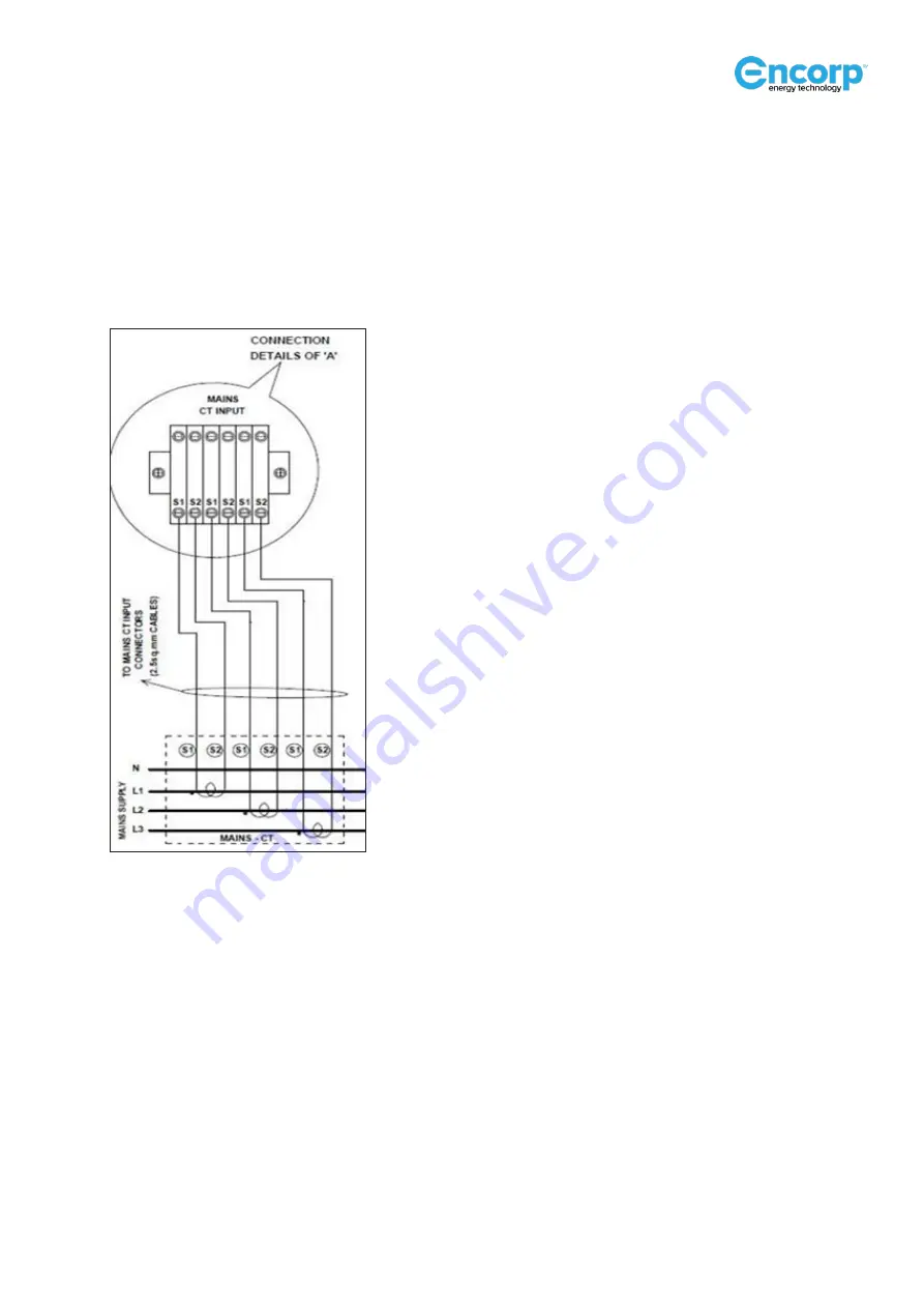
The CT terminals (usually marked S1 & S2 and the direction of CT current flow is marked P1 & P2) must be
connected to the CT terminal block in the iSAVER unit in exactly the same sequence. Check the schematic for
further clarity. (Example: The R phase CT to be connected to the R phase in the terminal block at the S1 & S2
connection point).
External CT Connection to iSAVER Models
• Similarly, connect the incoming supply main cables in the right sequence. Use only an approved cable with
suitable sizing for connecting from the main distribution to the iSAVER MCCB as shown in the connection
schematic.
•
Connect Ground for iSAVER with an approved cable of a suitable size.
• Color coding as per required electrical standards and codes is to be followed.
• It is extremely important to ensure that the external CT primary value is entered into the controller program
through HMI prior to startup to obtain the correct results and normal iSAVER operation.
Off-line Connection Verification
• Conduct a continuity test of each and every connection using a multi-meter to ensure that all the sequences
are correct as per the connection schematic (on page 8) and above procedure.
•
If any of the sequence is found to be incorrect, iSAVER will not work properly. It is mandatory to correct the
connections.


