


1616-964-12
Date: 7/27/2011
Rev. 2.1
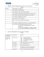
Pin
Description
Flow
47
Data out Hi – Diagnostics output
Out
48
RS232 #2 Hi – Messenger output
Out
49
Data in Hi – Diagnostics input
In
50
RS232 #2 Hi – Messenger input
In
51
PC S RX (Data Connections only)
In
52
RS232 #1 Hi – Serial G.P.S. input
In
53
Program-md1-- Factory Use Do Not
Connect
54
Program-RST-- Factory Use Do Not
Connect
55
Event switch #8 – Gnd=Active,
configuration. switch style
(mom,alt,dial,sqt)
In
56
Event switch #7 – same as pin 55
In
57
Event switch #6 – same as pin 55
In
58
Event switch #5 – same as pin 55
In
59
Event switch #4 – same as pin 55
In
60
Event switch #3 – same as pin 55
In
61
Event switch #2 – same as pin 55
In
62
11-33VDC positive voltage input
In
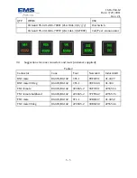
Figure 2
View of connector from rear (side contacts insert in)
3 - 11
Summary of Contents for Sky Connect Series
Page 8: ...1616 964 12 Date 7 27 2011 Rev 2 1 Figure 1 Tracker Communication Concept Drawing 1 2 ...
Page 20: ...1616 964 12 Date 7 27 2011 Rev 2 1 This page intentionally left blank 2 6 ...
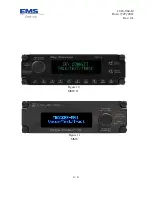
Page 36: ...1616 964 12 Date 7 27 2011 Rev 2 1 Figure 10 MMU II Figure 11 MMU 4 4 ...
Page 68: ......
Page 69: ......


