background image

32186-0-0513

Page 12

Figure 16

The correct pilot flame will be blue and extend past the thermopile 

as shown in the drawing.  LP gas models do not require adjusting.  

The input of Natural gas models will require adjusting if the inlet 

pressure to the valve is above 5" w.c.

pROpER MAIN bURNER FLAME 

5088, 7088

B

A

C

Figure 17


Inner Cone 

Outer Cone  Carry down flame

Model 

Gas 

(A) Dark blue  (B) Light blue  (C) Blue 


7088 

Nat 

1 inch 

2 1/2 inches  1/4 inch


LP 

3/4 inch 

2 inches 

small cone

5088 

Nat. 

3/4 inch 

2 inches 

3/16 inch


LP 

1/2 inch 

1 1/2 inch 

small cone

DO NOT MISTAkE AN ORANGE FLAME CAUSED BY PARTICLES 

IN THE AIR FOR THE UNDESIRABLE YELLOW FLAME.

FLAME 360° AROUND

GENERATOR - COMING

TO TOP OF GENERATOR

Figure 18

pROpER pILOt bURNER FLAME 5088, 7088

A blue flame shooting toward the main burner with an inner blue 

cone and a larger light blue outer flame. The generator will be sur

-

rounded by a blue flame that terminates near the top of the generator.

HIGH ALtItUdEs

Orifice size must be reduced for high altitude use, or carbon monoxide 

may be generated and excessive heat will seriously damage the unit.  

When altitudes over 2,000 feet are specified, in the United States, 

main burner spuds will be furnished to reduce input 4% for each 

1,000 feet of altitude above sea level.  Contact the manufacturer 

or your gas company before changing spud sizes.

CHECkING MANIFOLd pREssURE

Both Propane and Natural gas valves have a built-in pressure 

regulator in the gas valve with factory-set adjustment. Natural gas 

models should have a manifold pressure of approximately 3.5" 

w.c. at the valve outlet with the inlet pressure to the valve from a 

minimum of 5.0" w.c. for the purpose of input of input adjustment to 

a maximum of 7.0" w.c. Propane gas models will have a manifold 

pressure approximately 10.0" w.c. at the valve outlet with the inlet 

pressure to the valve from a minimum of 11.0" w.c.  for the purpose 

of input adjustment to a maximum of 13.0" w.c.
An 1/8" N.P.T. plugged tapping, accessible for test gage connection, 

is located on the outlet side of the gas control.

CLEANING tHE MAIN bURNER

Remove the burner and apply air pressure inside the throat of the 

burner and down into the ports.

Check for proper burner and pilot flame before and during each 

heating season.

sERvICING

INstALLAtION ANd REpAIR sHOULd bE dONE bY A qUALI-

FIEd sERvICE pERsON. 

The appliance should be inspected 

before use and at least annually by a professional service person. 

More frequent cleaning may be required due to excessive lint from 

carpeting, bedding material, etc. It is imperative that control compart-

ments, burners and circulating air passageways of the appliance 

be kept clean.

Floor furnace must not be connected to a chimney flue servicing 

a separate solid-fuel burning appliance.

dON't

 put anything around the furnace that will obstruct the 

flow of combustion and ventilation air.

DO keep the appliance area clear and free from combustible 

material, gasoline and other flammable vapors and liquids.

DO examine venting system periodically and replace damaged 

parts.

DO examine burners periodically. Clean and replace damaged 

parts.

MAkE

 periodic visual check of pilot and burner flame.

Summary of Contents for 3588-4

Page 1: ...tructions are not followed exactly a fire or explosion may result causing property damage personal injury or loss of life Do not store or use gasoline or other flammable vapors and liquids in the vici...

Page 2: ...This series is design certified in accordance withAmerican National Standard Z21 86b 2002 by the Canadian Standards Association as a gravity type Floor Furnace and must be installed according to these...

Page 3: ...be required due to excessive lint from carpeting bedding materials etc It is imperative thatcontrolcompartments burners andcirculating air passageways of the appliance be kept clean Do not use this h...

Page 4: ...as can adsorb or absorb onto or into walls masonry and other materials and fabrics in a room That will take some of the odorant out of the gas reducing its odor intensity LP Gas may stratify in a clos...

Page 5: ...sulated single wall metal pipe shall not be used outdoors in cold climates for venting gas utilization equipment 4 For flue pipe running through walls roof and within one 1 inch of combustible constru...

Page 6: ...the roof through a closet re member that you MUST keep a minimum distance of 1 inch between Type B vent pipe and any combustible material See Figure 9 Run it through a single wall pipe that is 2 inche...

Page 7: ...ion the additional furnace support and then nail the support in place by driving three nails into each end of it through the headers See Figure 10 12 Remove the jacks and supports 13 Make sure the fur...

Page 8: ...ce between two joists because location is critical See Figure 10 If the location is not critical it is easier for you to put the furnace against a joist and then fill in with one additional support Do...

Page 9: ...nominal pipe thread Use at least 1 2 inch pipe to avoid excessive pressure drop check lo cal codes Install the piping in accordance with the requirements described in Installation Planning Compounds...

Page 10: ...average with the thermostat ON 140 minimum for valve to open 65 minimum for pilot to stay on Caution Label all wires prior to disconnection when servic ing controls Wiring errors can cause improper an...

Page 11: ...TE The gas control rod is attached to the gas control knob 4 Push in gas control rod slightly and turn clockwise to OFF Note Rod cannot be turned from PILOT to OFF un less rod is pushed in slightly Do...

Page 12: ...ural gas models should have a manifold pressure of approximately 3 5 w c at the valve outlet with the inlet pressure to the valve from a minimum of 5 0 w c for the purpose of input of input adjustment...

Page 13: ...ust Street Hartford CT 06114 Phone 860 722 2433 Toll Free 800 243 9360 Fax 860 293 0479 Toll Free Fax 800 274 2004 Websites www fwwebb com www victormfg com Parts Heater Hearth and Grills MASTER PARTS...

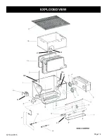
Page 14: ...32186 0 0513 Page 14 20 21 22A 22B 23 24 25 EXPLODED VIEW...

Page 15: ...15L PILOT BURNER WITH THERMOPILE LP GAS 12 602032 23218 23217 BURNER 13 732010 FF250 FF250 ELECTRODE AND WIRE 14 R2313 R2313 R2313 PIEZO IGNITOR 15 742169 P8631 P8625 BURNER ORIFICE NATURAL GAS 15 742...

Page 16: ...ppliance for service What Is Not Covered Damages that might result from the use misuse or improper installation of this appliance Travel diagnostic costs and freight charges on warranted parts to and...

Reviews: