


4
capacitors. Use a function appropriate for the given measure-
ment. Before changing the range (or switching functions) dis-
connect the conductors from the circuit that is being measured.
• Make sure the device is undamaged before you begin using the
multimeter. If you find obvious signs of damage on the body of
the device, do not make any measurements! Check that the
surface of the multimeter does not have scratches and that the
side joints are not coming apart.
• Also check the insulation on the measuring probes. Damaged
insulation may result in injury by electric current. Do not use
damaged measuring probes!
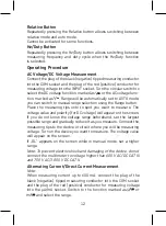
• Do not measure voltages above 1 000 V! If you intend to measure
current, check the multimeter‘s fuse and turn off the power
supply to the circuit before you connect the multimeter. Before
measuring, make sure the circular switch for setting measuring
range is in the correct position. Under no circumstances should
you make any changes to the measuring range (by moving the
circular switch for changing measuring programmes) while
measuring! Doing so could damage the device. When you are
measuring, first connect the black conductor (probe) and then
the red conductor (probe). When disconnecting the testing
conductors, disconnect the red one first.
• If you find that the multimeter is making abnormal measure-
ments, stop using it. The fuse may be damaged. If you are unsure
of the cause of the defect, contact a service centre.
• Do not measure voltages higher than listed on the front panel
of the multimeter. Risk of injury by electric current or damage
to the multimeter!
• Check that the multimeter is working properly before use. Test
on a circuit with known electrical values.
• Before you connect the multimeter to a circuit you intend to
measure, turn off the power to the circuit.
• Do not use or store the multimeter in environments with high
temperature, dust or humidity. It is also not recommended to
use the device in environments with potentially strong magnetic
fields or risk of explosion or fire.
Summary of Contents for M0430
Page 2: ...2 1 2 3 9 4 8 5 10 7 6 1...
Page 114: ...114 CAT II IV M0430 1 000...
Page 115: ...115 30 V AC rms 42 60 DC...
Page 116: ...116 9 1604 6F22 AC DC AC DC...
Page 124: ...124 OL WH3303 DM633 10 AC 1 COM INPUT 2 3 1 1 1 2 1 1 COM INPUT Select 30...
Page 125: ...125 COM INPUT Select OL 1 1 M 2 OL COM INPUT Select OL 1 hFE 2 COM INPUT 2 3 NPN PNP...
Page 126: ...126 4 hFE 2 A B 1 Select C F 2 COM K INPUT 3 K 20 C 300 C 300 C 1 COM INPUT 2 3...
Page 181: ...181 BG M0430 EN 61010 1 CAT III 600 V CAT II 1 000 V 2 CAT III CAT II IV M0430...
Page 182: ...182 1 000 V...
Page 183: ...183 30 V 42 V 60 V...
Page 184: ...184 9 V 6F22 1604 C F 1 M0430 5...
Page 191: ...191 Relative Relative Hz Duty Hz Duty Hz Duty COM INPUT AUTO Range OL 600 V...
Page 193: ...193 1 1 A 1 mV 2 1 A 1 mV COM INPUT Select 30 COM INPUT Select OL 1 1 M...
Page 195: ...195 3 K 20 C 300 C 300 C 1 COM INPUT 2 3 600 F 10...
Page 196: ...196 1 COM INPUT 2 3 4 Hz Duty EMOS spol s r o Lipnick 2844 750 02 P erov...
Page 197: ...197...
Page 198: ...198...
Page 199: ...199...