


14
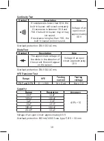
Continuity Test
Connect the plug of the black (negative) tipped measuring conductor
into the COM socket and the plug of the red (positive) conductor for
measuring voltage into the INPUT socket. Switch to the function
marked with
. Press the
Select
button repeatedly to select the
function. Connect the measuring tips to the circuit you want to
measure. The buzzer will sound if the resistance of the measured
circuit is lower than 30 Ω.
Note: Before testing, disconnect all power supply from the circuit you
want to test and thoroughly discharge all capacitors.
Resistance Measurement
Connect the plug of the black (negative) tipped measuring conductor
into the COM socket and the plug of the red (positive) conductor for
measuring voltage into the INPUT socket. Switch to the function
marked with
. Press the
Select
button repeatedly to select
the function. Connect the measuring tips to the object you want
to measure (resistor). The measured resistance value will appear
on the screen. If the „OL“ symbol appears on the screen, switch to
a higher range.
N
ote:
1. When measuring resistances higher than 1 MΩ, it is necessary
to wait a few seconds before the measured value stabilizes.
2. If the circuit is open, the „OL“ symbol will appear, same as when
the measuring range is exceeded. Before measuring resistance,
make sure that the measured object is disconnected from power
supply and all its capacitors are fully discharged.
Diode Measurement
Connect the plug of the black (negative) measuring conductor into
the COM socket and the plug of the red (positive) measuring tip for
measuring diodes into the INPUT socket. Switch to the function
marked with
. Press the
Select
button repeatedly to select the
function. Connect the red measuring tip onto the diode‘s anode
and the black measuring tip onto the diode‘s cathode. Approximate
voltage in the direction of the flow of current will appear on the
screen. „OL“ will appear on the screen if the polarity is reversed.
Summary of Contents for M0430
Page 2: ...2 1 2 3 9 4 8 5 10 7 6 1...
Page 114: ...114 CAT II IV M0430 1 000...
Page 115: ...115 30 V AC rms 42 60 DC...
Page 116: ...116 9 1604 6F22 AC DC AC DC...
Page 124: ...124 OL WH3303 DM633 10 AC 1 COM INPUT 2 3 1 1 1 2 1 1 COM INPUT Select 30...
Page 125: ...125 COM INPUT Select OL 1 1 M 2 OL COM INPUT Select OL 1 hFE 2 COM INPUT 2 3 NPN PNP...
Page 126: ...126 4 hFE 2 A B 1 Select C F 2 COM K INPUT 3 K 20 C 300 C 300 C 1 COM INPUT 2 3...
Page 181: ...181 BG M0430 EN 61010 1 CAT III 600 V CAT II 1 000 V 2 CAT III CAT II IV M0430...
Page 182: ...182 1 000 V...
Page 183: ...183 30 V 42 V 60 V...
Page 184: ...184 9 V 6F22 1604 C F 1 M0430 5...
Page 191: ...191 Relative Relative Hz Duty Hz Duty Hz Duty COM INPUT AUTO Range OL 600 V...
Page 193: ...193 1 1 A 1 mV 2 1 A 1 mV COM INPUT Select 30 COM INPUT Select OL 1 1 M...
Page 195: ...195 3 K 20 C 300 C 300 C 1 COM INPUT 2 3 600 F 10...
Page 196: ...196 1 COM INPUT 2 3 4 Hz Duty EMOS spol s r o Lipnick 2844 750 02 P erov...
Page 197: ...197...
Page 198: ...198...
Page 199: ...199...